3 usb device connection, Figure 3-26: serial device connector – IEI Integration AFL-19i-HM55 v1.01 User Manual
Page 59
AFL-HM55 Series Panel PC
Page 47
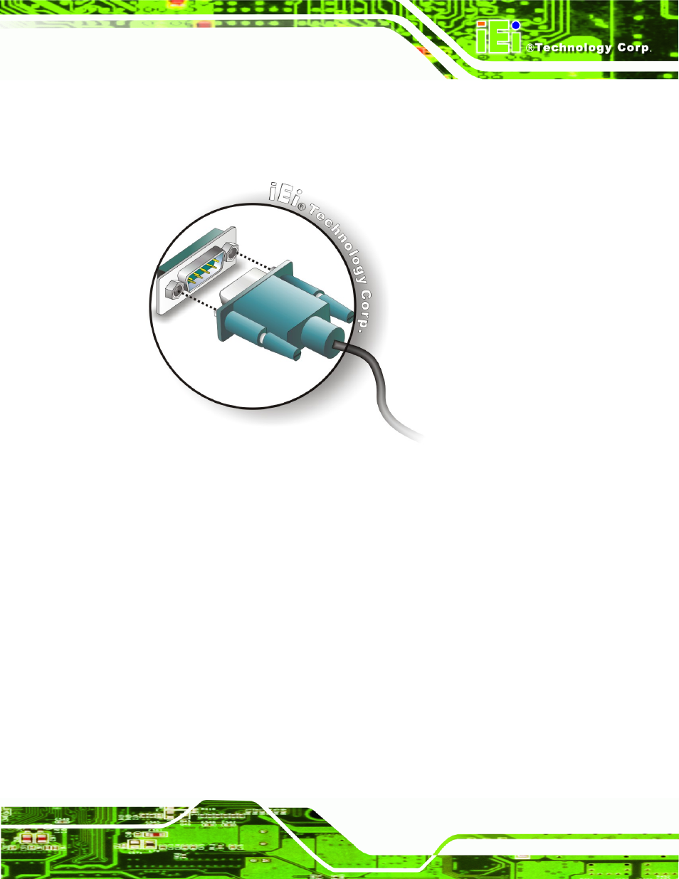
Locate the DB-9 connector
. The location of the DB-9 connector is shown in Chapter 2.
Insert the serial connector
. Insert the DB-9 connector of a serial device into the DB-9
connector on the bottom panel. See Figure 3-26.
Figure 3-26: Serial Device Connector
Secure the connector
. Secure the serial device connector to the external interface by
tightening the two retention screws on either side of the connector.
3.11.3 USB Device Connection
There are four external USB 2.0 connectors. All connectors are perpendicular to the
AFL-HM55 Series. To connect a USB 2.0 or USB 1.1 device, please follow the instructions
below.
Located the USB connectors
. The locations of the USB connectors are shown in
Chapter 2
.
Align the connectors.
Align the USB device connector with one of the connectors on the
bottom panel. See Figure 3-27.