Figure 3-7: jp7 jumper setting location, Table 3-4: com1 pin 9 setting jumper settings, Table 3-5: com3 pin 9 setting jumper settings – IEI Integration AFL-19i-HM55 v1.01 User Manual
Page 41: Afl-hm55 series panel pc page 29
AFL-HM55 Series Panel PC
Page 29
JP7 Description
Short 1-2
COM1 RI +12 V
Short 3-4
COM1 RI Normal
Short 5-6
COM1 RI Pin +5 V
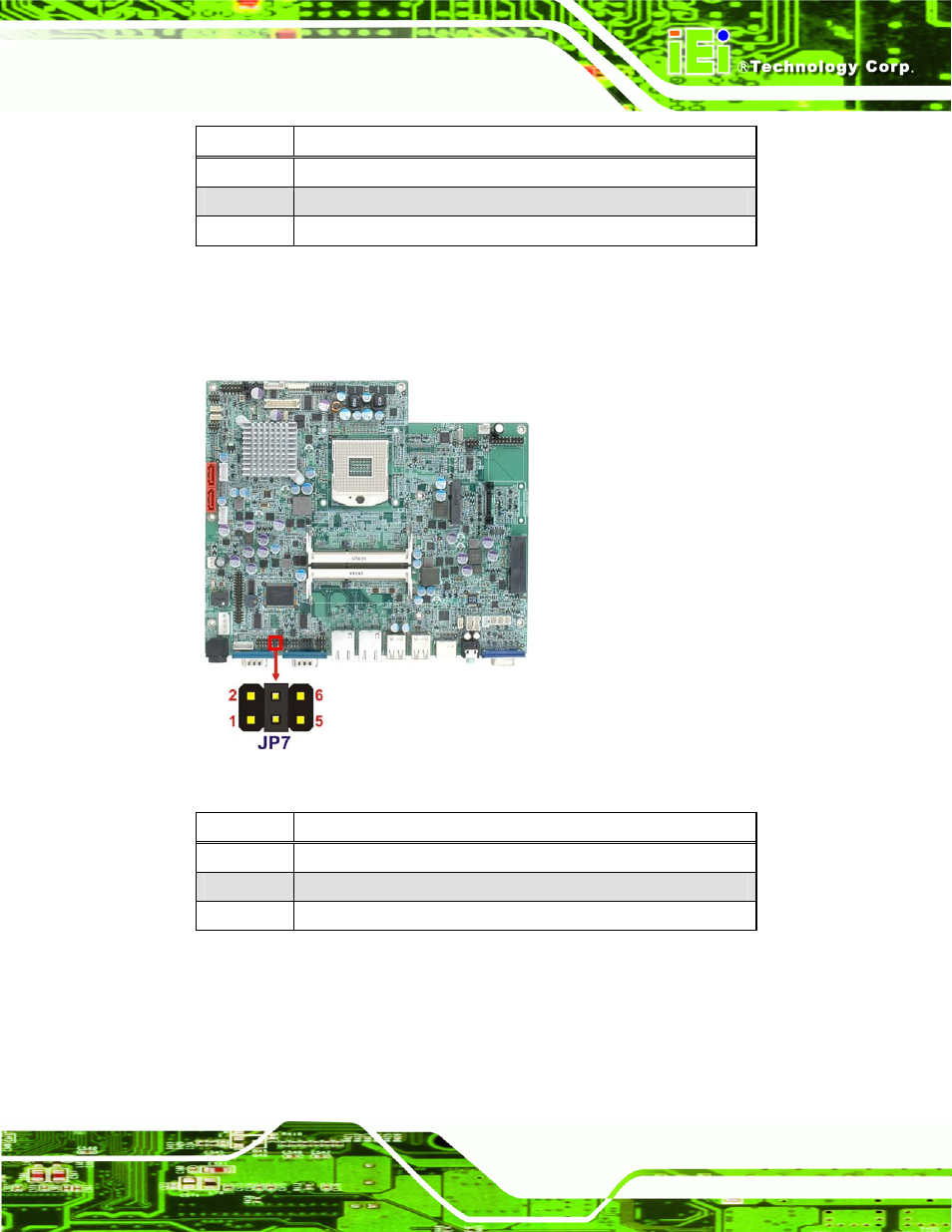
Table 3-4: COM1 Pin 9 Setting Jumper Settings
The JP7 jumper location is shown below.
Figure 3-7: JP7 Jumper Setting Location
JP8 Description
Short 1-2
COM3 RI +12 V
Short 3-4
COM3 RI Normal
Short 5-6
COM3 RI +5 V
Table 3-5: COM3 Pin 9 Setting Jumper Settings
The JP8 jumper location is shown below.
This manual is related to the following products: