5 3-pin power terminal block, Figure 3-11: rj-45 ethernet connector, Figure 3-12: 3-pin terminal block pinout location – IEI Integration TANK-101B-D525_N455 v1.00 User Manual
Page 34: Table 3-4: rj-45 ethernet connector leds
TANK-101B/BW Em b e d d e d S ys te m
P a g e 24
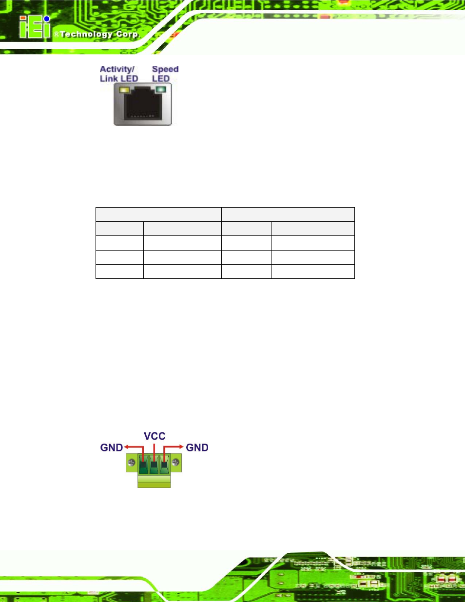
Figure 3-11: RJ-45 Ethernet Connector
The RJ-45 Ethernet connector has two status LEDs, one green and one yellow. The green
LED indicates activity on the port and the yellow LED indicates the port is linked. See
Activity/Link LED
Speed LED
STATUS
DESCRIPTION
STATUS
DESCRIPTION
Off
No link
Off
10 Mbps connection
Yellow
Linked
Green
100 Mbps connection
Blinking
TX/RX activity
Orange
1 Gbps connection
Table 3-4: RJ-45 Ethernet Connector LEDs
3.7.5 3-p in P o we r Te rm in a l Blo c k
CN Typ e :
3-pin terminal block
CN Lo c a tio n :
N P in o u ts :
Connect the leads of a 9V~36V DC power supply into the terminal block. Make sure that
the power and ground wires are attached to the correct sockets of the connector.
Figure 3-12: 3-pin Terminal Block Pinout Location