5 mounting the system with wall mount kit, Ounting the, Ystem with – IEI Integration TANK-101B-D525_N455 v1.00 User Manual
Page 27: Ount, Figure 3-5: retention screw holes
TANK-101B/BW Em b e d d e d S ys te m
P a g e 17
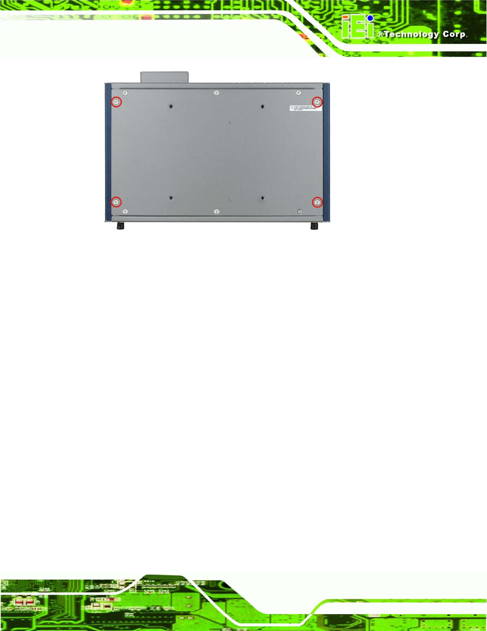
Figure 3-5: Retention Screw Holes
S te p 3:
Secure the brackets to the system by inserting two retention screws into each
bracket.
S te p 4:
Drill holes in the intended installation surface.
S te p 5:
Align the mounting holes in the sides of the mounting brackets with the predrilled
holes in the mounting surface.
S te p 6:
Insert four retention screws, two in each bracket, to secure the system to the
wall.
3.5 Mo u n tin g th e S ys te m with Wa ll Mo u n t Kit
To mount the embedded system onto a wall using the VESA MIS-D 100 wall mount kit,
please follow the steps below.
S te p 1:
Select the location on the wall for the wall-mounting bracket.
S te p 2:
Carefully mark the locations of the four bracket screw holes on the wall.
S te p 3:
Drill four pilot holes at the marked locations on the wall for the bracket retention
screws.
S te p 4:
Align the wall-mounting bracket screw holes with the pilot holes.