C.1 introduction, C.2 dio connector pinouts, C.3 assembly language samples – IEI Integration IMBA-XQ354 v1.10 User Manual
Page 216: C.3.1 enable the dio input function, Ntroduction, Onnector, Inouts, Ssembly, Anguage, Amples
IMBA-XQ354 Motherboard
Page 196
C.1 Introduction
The DIO connector is interfaced to GPIO ports on the Super I/O chipset. The DIO has both
4-bit digital inputs and 4-bit digital outputs. The digital inputs and digital outputs are
generally control signals that control the on/off circuit of external devices or TTL devices.
Data can be read or written to the selected address to enable the DIO functions.
NOTE:
For further information, please refer to the datasheet for the Super I/O
chipset.
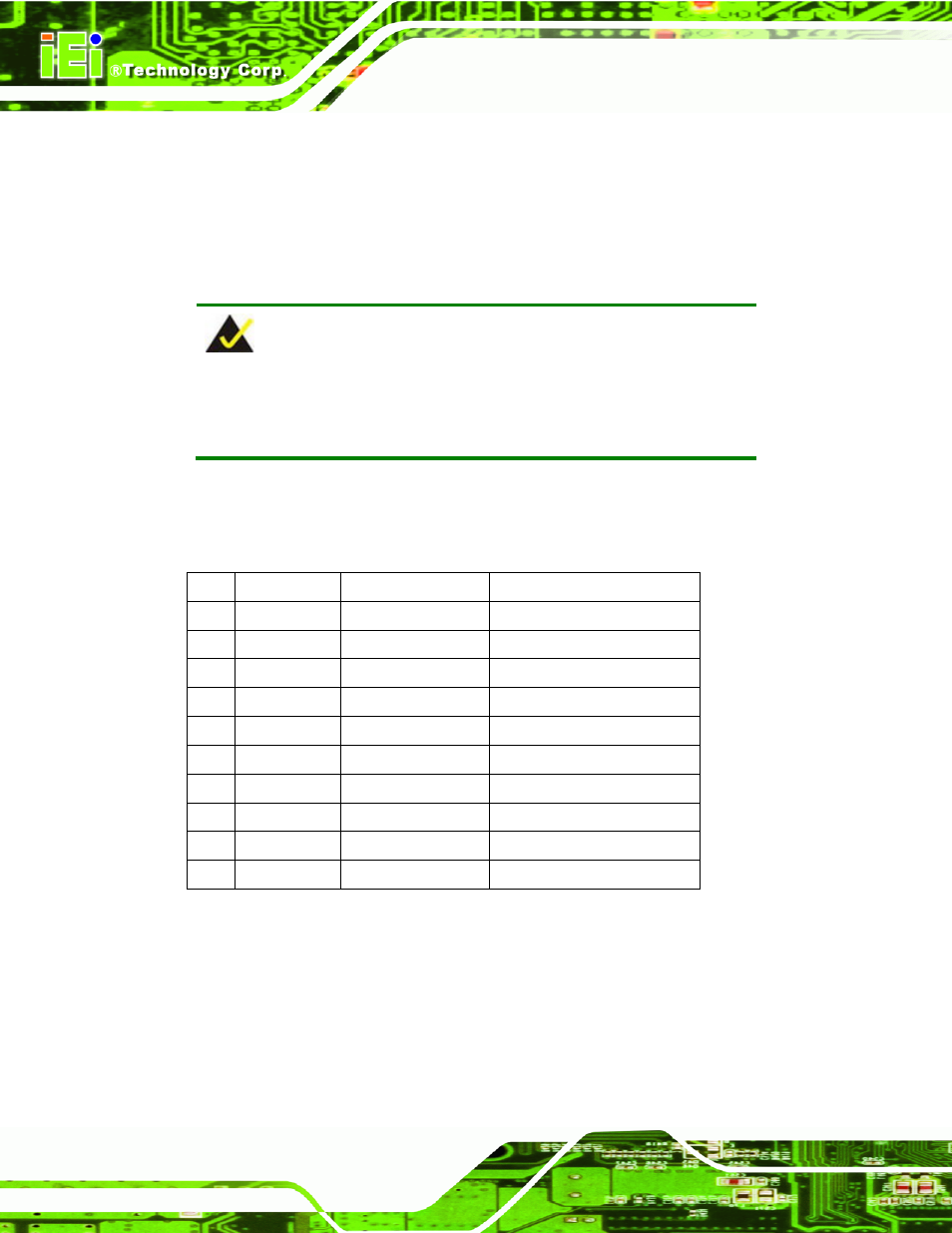
C.2 DIO Connector Pinouts
The Digital I/O port pins and their pin numbers are listed in the table below.
Pin
Description
Super I/O Pin No
Super I/O Pin Description
1
Ground
N/A
N/A
2
VCC
N/A
N/A
3
Output 3
20
GP27
4
Output 2
21
GP26
5
Output 1
22
GP25
6
Output 0
23
GP24
7
Input 3
24
GP23
8
Input 2
25
GP22
9
Input 1
26
GP21
10
Input 0
27
GP20
Table C-1: Digital I/O Connector Pinouts
C.3 Assembly Language Samples
C.3.1 Enable the DIO Input Function
The BIOS interrupt call INT 15H controls the digital I/O. An assembly program to enable
digital I/O input functions is listed below.