6 external peripheral interface connection, 1 lan connection, Xternal – IEI Integration PCISA-PV-D4251_N4551_D5251 User Manual
Page 68: Eripheral, Nterface, Onnection, Figure 4-11: dual usb cable connection
PCISA-PV-D4251/N4551/D5251 CPU Card
Page 55
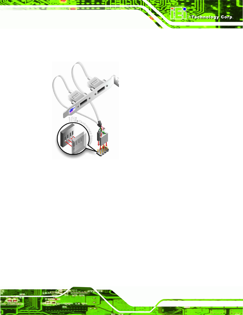
Step 3:
Insert the cable connectors
.
Once the cable connectors are properly aligned
with the USB connectors on the PCISA-PV-D4251/N4551/D5251, connect the
cable connectors to the on-board connectors. See Figure 4-11.
Figure 4-11: Dual USB Cable Connection
Step 4:
Attach the bracket to the chassis. The USB 2.0 connectors are attached to a
bracket. To secure the bracket to the chassis please refer to the installation
instructions that came with the chassis.
Step 0:
4.6 External Peripheral Interface Connection
This section describes connecting devices to the external connectors on the
PCISA-PV-D4251/N4551/D5251.
4.6.1 LAN Connection
There are two external RJ-45 LAN connectors. The RJ-45 connectors enable connection
to an external network. To connect a LAN cable with an RJ-45 connector, please follow
the instructions below.