Figure 3-24: rj-45 ethernet connector, Table 3-25: lan1 and lan2 pinouts, Table 3-26: rj-45 ethernet connector leds – IEI Integration PCISA-PV-D4251_N4551_D5251 User Manual
Page 51: See table 3-25
PCISA-PV-D4251/N4551/D5251 CPU Card
Page 38
There are two LEDs on the connector indicating the status of LAN. The pin assignments
are listed in the following table:
PIN DESCRIPTION PIN
DESCRIPTION
1 LAN#_MDI0+ 10
LAN_MDI3-
2 LAN#_MDI0- 11
LAN#_LINK100
3 LAN#_MDI1+ 12
LAN#_LED3/EEDO
4 LAN#_MDI1- 13
LAN#_ACT-1
5 GND
14
VCC
6 GND
15
GND
7 LAN#_MDI2+ 16
GND
8 LAN#_MDI2- 17
NC
9 LAN#_MDI3+ 18
NC
Table 3-25: LAN1 and LAN2 Pinouts
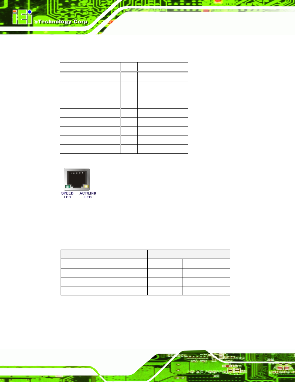
Figure 3-24: RJ-45 Ethernet Connector
The RJ-45 Ethernet connector has two status LEDs, one green and one yellow. The green
LED indicates activity on the port and the yellow LED indicates the port is linked. See
SPEED LED
ACT/LINK LED
STATUS DESCRIPTION STATUS DESCRIPTION
OFF
10Mbps connection
OFF
No link
GREEN
100Mbps connection
YELLOW
Linked
ORANGE
1Gbps connection
BLINKING
Data Activity
Table 3-26: RJ-45 Ethernet Connector LEDs