3 external interface panel connectors, 2 internal peripheral connectors, 1 atx power supply enable connector – IEI Integration PCISA-PV-D4251_N4551_D5251 User Manual
Page 30: Nternal, Eripheral, Onnectors, Table 3–2: external peripheral connectors
PCISA-PV-D4251/N4551/D5251 CPU Card
Page 17
3.1.3 External Interface Panel Connectors
The table below lists the connectors on the external I/O panel.
Connector
Type
Label
CRT connector
15-pin female
connector
VGA1
Ethernet connector (1)
RJ-45 connector
LAN1
Ethernet connector (2)
RJ-45 connector
LAN2
USB 2.0 port (1)
USB port connector
USB_C1
USB 2.0 port (2)
USB port connector
USB_C2
Table 3–2: External Peripheral Connectors
3.2 Internal Peripheral Connectors
The section describes all of the connectors on the PCISA-PV-D4251/N4551/D5251.
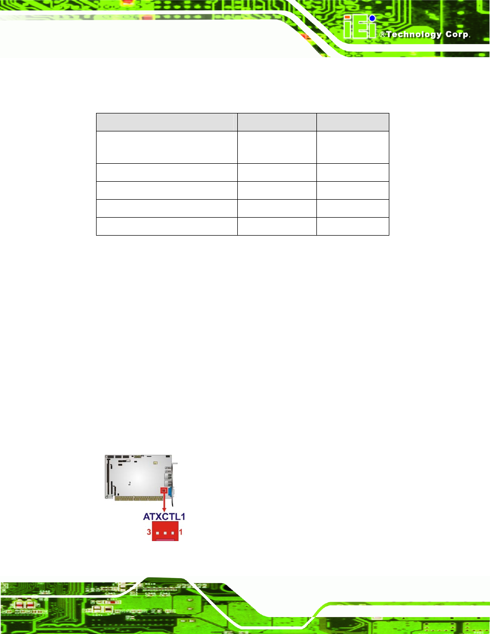
3.2.1 ATX Power Supply Enable Connector
CN Label:
ATXCTL1
CN Type:
3-pin wafer (1x3)
CN Location:
CN Pinouts:
The ATX power supply enable connector enables the PCISA-PV-D4251/N4551/D5251 to
be connected to an ATX power supply.
Figure 3-2: ATX Power Supply Enable Connector Location