Warner Electric MCS-131 User Manual
Page 7
50
6
0
50
6
0
0 to 6
CH1
(Clutch)
CH2
(Brake)
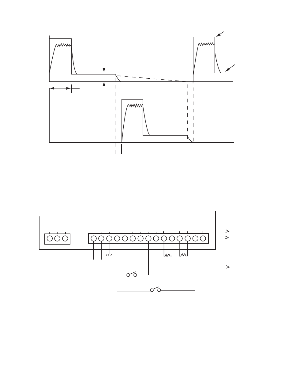
Adjustable Over Excitation
Time 2 to 14 MSEC.
Adjustable For
Steady State Output
0.1 10 17 MSEC.
Adjustable Delay
To Prevent Overlap
Current
Voltage
DC
+24V COM +4.8V
18 17 16
Switching
S1- Input Switch
Open - Channel 2 ON
Closed - Channel 1 ON
Inhibit Switch
Open - System Inhibited, Channel 1 ON
Clesed - Normal Operation
S2-
120 V
or
240V
AC
AC
Input
Earth
GND
DC
COM +12 V CH2 CH1 IN
N/C
-
-
+
+
CH2
CH1
INH N/C
S1
S2
MCS-131
TERMINAL DESIGNATIONS
1 NO. Connection
2 Inhibit
3
4
5
6
7 NO. Connection
8 Input
9 LED Channe1 1
10 LED Channel 2
11 +12 VDC Output
12 DC Common
13 Earth Ground
14
15
16 +4.8 VDC Output (Optional Board)
17 DC Common
18 +24 VDC Output
Channel 1 Output
Channel 2 Output
AC Input
15
14
13
12
11
10
9
8
7
6
5
4
3
2
1
LED
Figure 1 - Voltage and Current Waveforms
Figure 2 - Basic Control with Switch Inputs
Warner Electric • 800-825-9050
P-262 • 819-0493
6