Ssembly, Nstructions – Vestil SLG-6 & SLG-10 User Manual
Page 5
Copyright 2012 Vestil Manufacturing Corp.
Page 5 of 12
A
SSEMBLY
I
NSTRUCTIONS
:
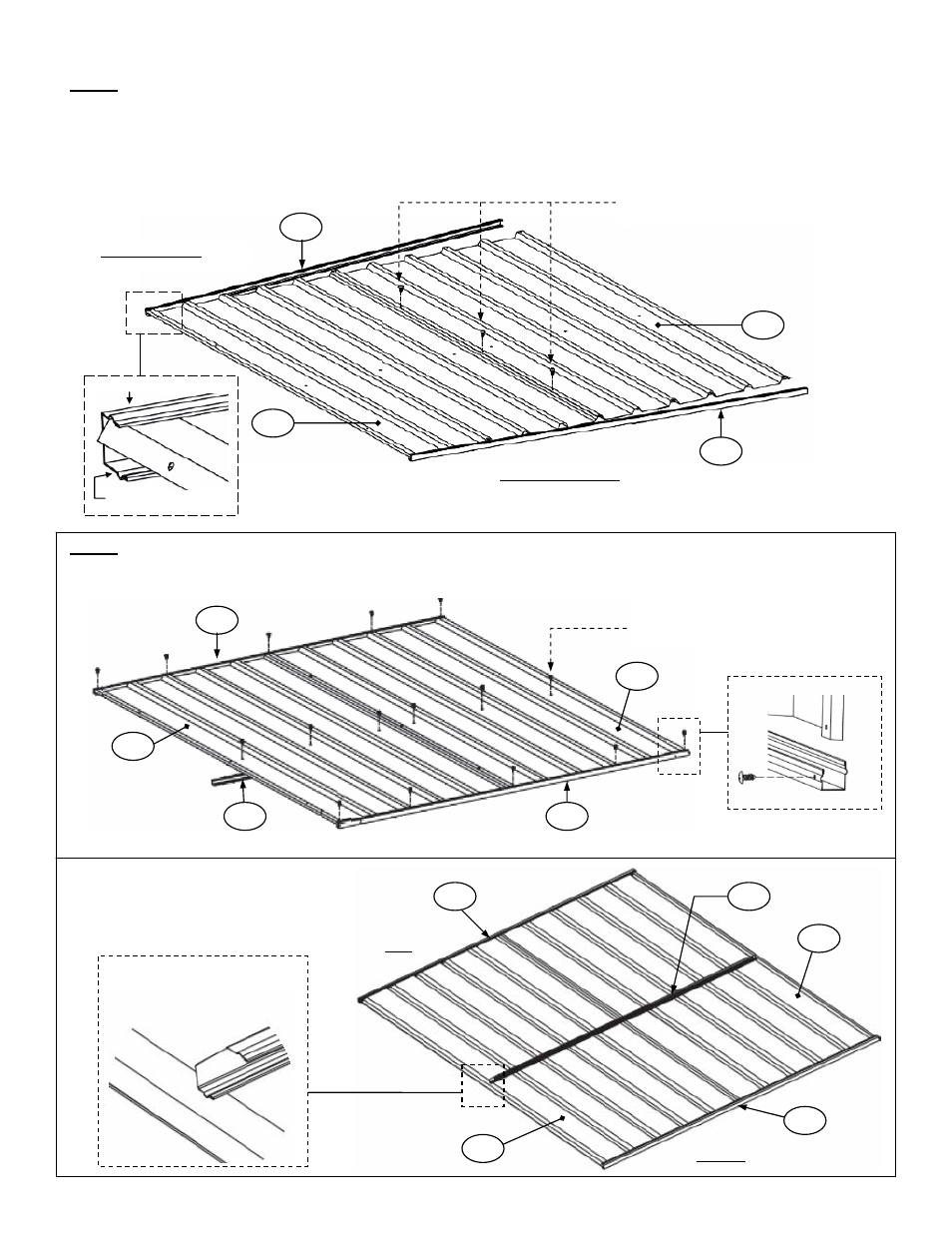
Step 1: Fasten rear panel 1R to panel 1L using 10mm self-tapping screws as depicted in the diagram below. Panels
are shown with the outside surface facing up (corrugations face upwards).
Connect top channel 20B to one side of the panels by either tapping the channel into place with a rubber mallet, or
sliding it into place. Connect bottom channel 20C to the opposite side of the panels. The top of the panels is the side
to which channel 20B is connected. NOTE: Channels 20B and 20C are not symmetrical. The shorter lip of each
channel must be on the outside surface.
Step 2: Fasten channels 20B and 20C to the rear panels with 10mm self-tapping screws; then fasten channel 31 to
the inside surface of the rear panels with 10mm self-tapping screws.
10mm self-tapping screws
20C
20B
1R
1L
Bottom of rear panels
Top of rear panels
Short lip
Long lip
This symbol indicates a place
where a 10mm screw should be
used to fasten channel to panel.
31
20B
20C
Fasten channel 38A with the slot
facing the bottom
Bottom
Top
View of inside surface of rear wall with channel
31 installed
1R
1L
1R
1L
20C
20B
31