Fig. 2: d-series hoppers diagram and parts list – Vestil D series hoppers User Manual
Page 6
11/4/2013
D & H series hoppers, manual
Copyright 2013 Vestil Manufacturing Corp.
Page 6 of 13
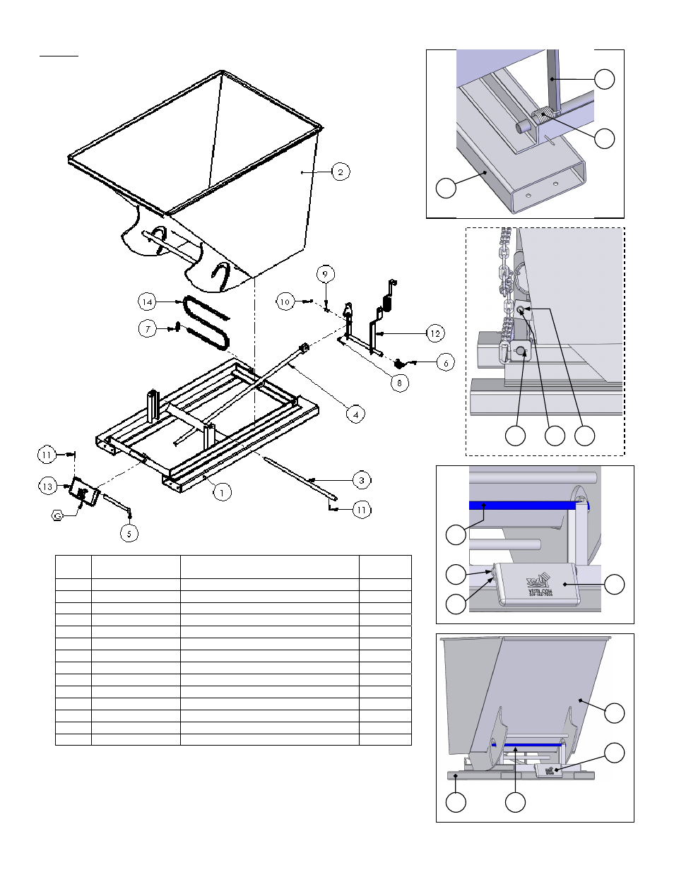
Fig. 2: D-series hoppers diagram and parts list
Item
No.
Part No.
Description
Quantity
1 37-514-004
Base
frame
weldment
1
2 37-545-046
Chute
weldment
1
3 37-112-007
Pivot
pin
1
4
37-537-006
Release lever rod weldment
1
5
37-112-006
Bumper plate pin
1
6
37-146-005
Chute release torsion spring
2
7 45214
5
/
16
in. quick link
1
8 65125
3
/
16
in. x 1½ in. zinc-plated cotter pin
1
9 01-112-009
Hinge
pin
2
10
68015
¾ in. external retaining ring
3
11 64141
3
/
16
in. x 2 in. spring pin
1
12 37-537-010
Chute
release
assembly
1
13
37-037-040
Chute release bumper plate
1
14 37-145-004
5
/
16
in. x 48in. safety chain
1
5
13
3
10
12
7
8
9
1
1
3
2
13
5