Fig. 1, H-series hoppers diagram and parts list – Vestil D series hoppers User Manual
Page 5
11/4/2013
D & H series hoppers, manual
Copyright 2013 Vestil Manufacturing Corp.
Page 5 of 13
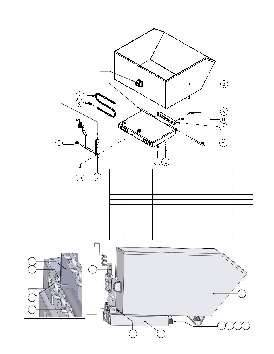
Fig. 1:
H-series hoppers diagram and parts list
4
7
8
11
12
10
3
2
1
3
6
5
Release latch bar
Release latch
lever
Item
no.
Part no.
Description
Quantity
1 37-514-005 Base
frame
weldment
1
2 37-545-008 Hopper
chute
weldment
1
3
37-537-010
Chute release lever weldment
1
4 37-146-005 Release
torsion
spring
1
5 37-145-002
5
/
16
in. x 57½in. safety chain
1
6 45214
5
/
16
in. quick link
2
7 29-048-061 Rubber
pumper
1
8 11061
5
/
16
in. – 18 x 2in. HHCS zinc-plated bolt
2
9 37-112-045 Pivot
pin
2
10 65127
3
/
16
in. x 2in. zinc-plated cotter pin
3
11 33006
5
/
16
in. USS zinc-plated flat washer
2
12 37021
5
/
16
in. – 18 nylock nut
2
Pivot pin channel