Vanguard WRM-40 User Manual
Page 27
REV 3 WRM-10P AND WRM-40 USER’S MANUAL
23
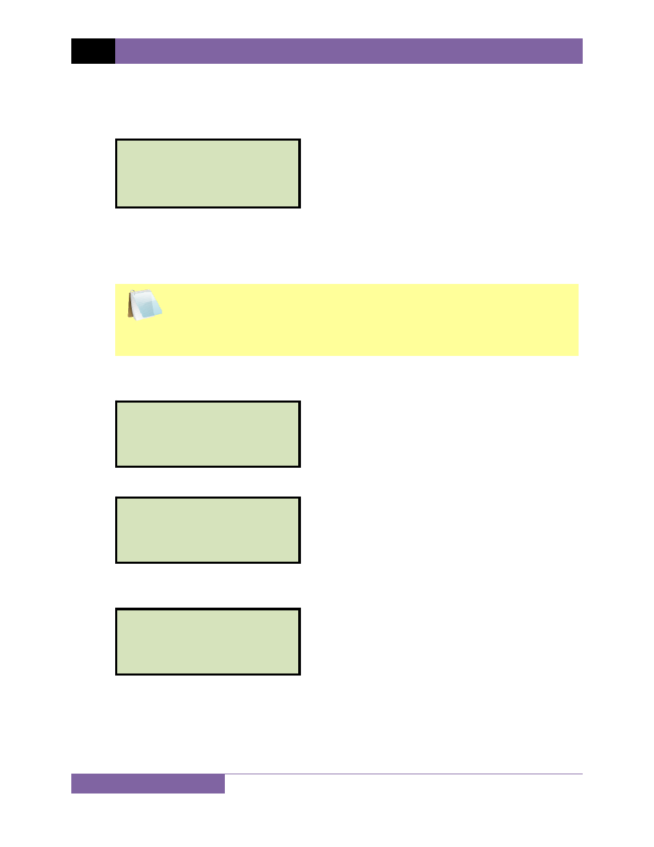
j. The WRM determines when the resistance reading is stable and displays the resistance
values on the LCD screen as shown below:
The WRM will continue the test and update the resistance values on the LCD screen.
While the test is in progress, you can press the
[ENTER]
key to save the current
readings from the LCD screen to the WRM’s internal working memory. This process can
be repeated as needed for a maximum of 48 times per test.
NOTE
Although this process can be used to store multiple readings when testing a
Load Tap Changer (LTC) or Voltage Regulator, a more convenient method is
also available. Please see section 3.5 for information about performing an
LTC or Voltage Regulator test.
If the
[ENTER]
key is pressed, the data is saved and the following screen will be
displayed on the LCD screen:
Once the data is saved, the following screen will be displayed:
Press the
[STOP]
key to stop running the test. The test results will be displayed as
shown:
Press any key to continue to the next step.
TEST RESULTS
I = 1.09A R1=499
μΩ
TEST SAVED
TEST IN PROGRESS
I = 1.09A R1=499
μΩ
TEST SAVED
* XFMR ENERGIZED! *
TEST IN PROGRESS
I = 1.09A R1=499
μΩ
SAVING TEST
* XFMR ENERGIZED! *
TEST IN PROGRESS
I=9.79A R1=499
μΩ
R2=105
μΩ
* XFMR ENERGIZED! *