Connection examples, Terminal layout mode selection operation, Transfer characteristics – TREND RN User Manual
Page 5
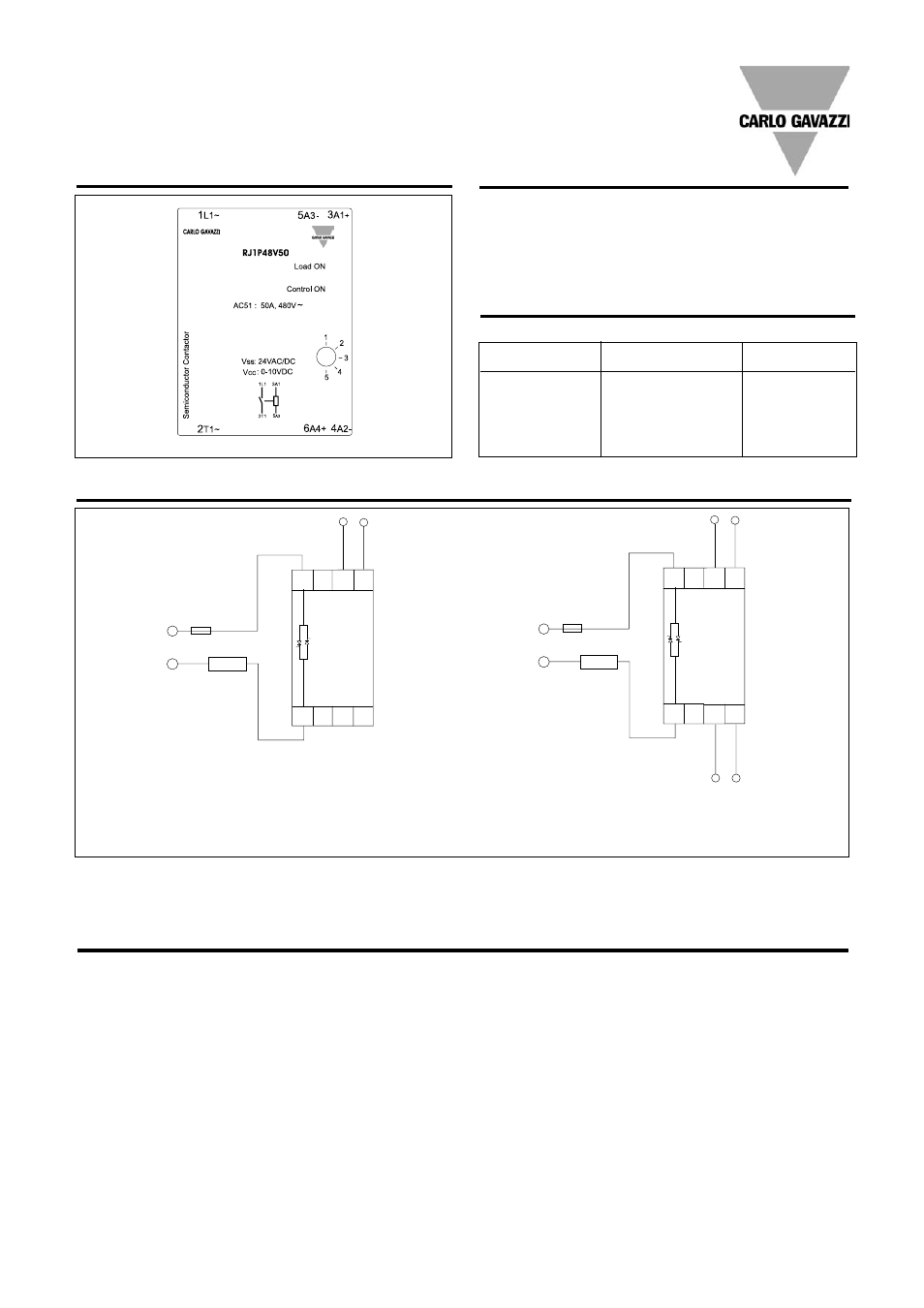
Example: RJ1P48I50E
Example: RJ1P48V50E
~
~
-
+
LOAD
4 - 20mA
2T1
1L1
5A3 3A1
4A2
6A4
~
~
LOAD
+
10VDC
2T1
1L1
5A3 3A1
4A2
6A4
+
0V
24VDC/AC
-
0V
-
Specifications are subject to change without notice (27.06.2006)
3
RJ1P
Connection Examples
3A1 - 5A3: Control input current
3A1 - 5A3: Control input voltage, Vcc
4A2 - 6A4: Supply input voltage, Vss
LED INDICATION
The top Red LED indicates the
load status. It goes ON when-
ever the load is activated. The
Green LED gives indication of
the status of the control input.
Upon application of control
current (for the RJ1P..I...) to
terminals A1-A3, the Green
LED will be dimly lit, with its
intensity increasing with an
increase in control current.
For the RJ1P..V..., the Green
LED will be ON (flickering)
upon application of the supply
voltage to terminals A2 - A4.
Once a control voltage is
applied to terminals A1 - A3,
the Green LED will be fully ON,
if greater than a threshold volt-
age (approx. 0.5V). Note that
the first time the device (volt-
age control version) is to be
activated, the mains voltage
has to be present for the
Green LED to indicate the
control status.
Terminal Layout
Mode Selection
Operation
MODE
Transfer characteristics
Control
Control
Output
Current (mA)
Voltage (VDC)
Power (%)
4
0
0
8
2.5
25
12
5
50
16
7.5
75
20
10
99
Output power as a function of control input
MODE 1
Phase Angle Switching
MODE 2
Distributed Control
MODE 3
Burst Switching (1 sec. period)
MODE 4
Burst Switching (3 sec. period)
MODE 5
Burst Switching (10 sec. period)
MODE 1: The Phase Angle
switching mode works in
accordance with the phase
angle control principle, i.e. the
output switching point in the
AC sine wave depends on the
signal level applied at the
input. The relay switches off
everytime the output current
crosses zero.
MODE 2: The Distributed
mode provides a number of
full cycles, evenly distributed
over a fixed period of 1.28s @
50Hz (1.07s @ 60Hz), depend-
ing on the control input.
MODE 3, 4, 5: The Burst
Switching mode generates a
number of full cycles, depend-
ing on the control input over
fixed periods of 1s, 3s or 10s
for MODES 3, 4 and 5 respec-
tively.
Modes 2, 3, 4 and 5 use the
zero switching principle, thus
ensuring a reduced level of
radiated and wire-conducted
noise. The Distributed and
Burst Switching modes are not
recommended for light control
due to light-flickering.
Note: For the RJ1P..V..., it is possible to have the ground terminals of the supply and control power supplies used commoned. In the case, this common
ground is connected either to terminal A2 or terminal A3. This is only applicable when a 24 VDC supply voltage is used. There should be no external direct
link from terminal A2 to Terminal A3.