Functional diagrams applications terminal layout – TREND RN User Manual
Page 11
4
Specifications are subject to change without notice (30.09.2005)
VAC / VDC
A
2
X
X
+
_
A
3
A
4
L
1
T
1
C/V
L
2
T
2
X
X
A
1
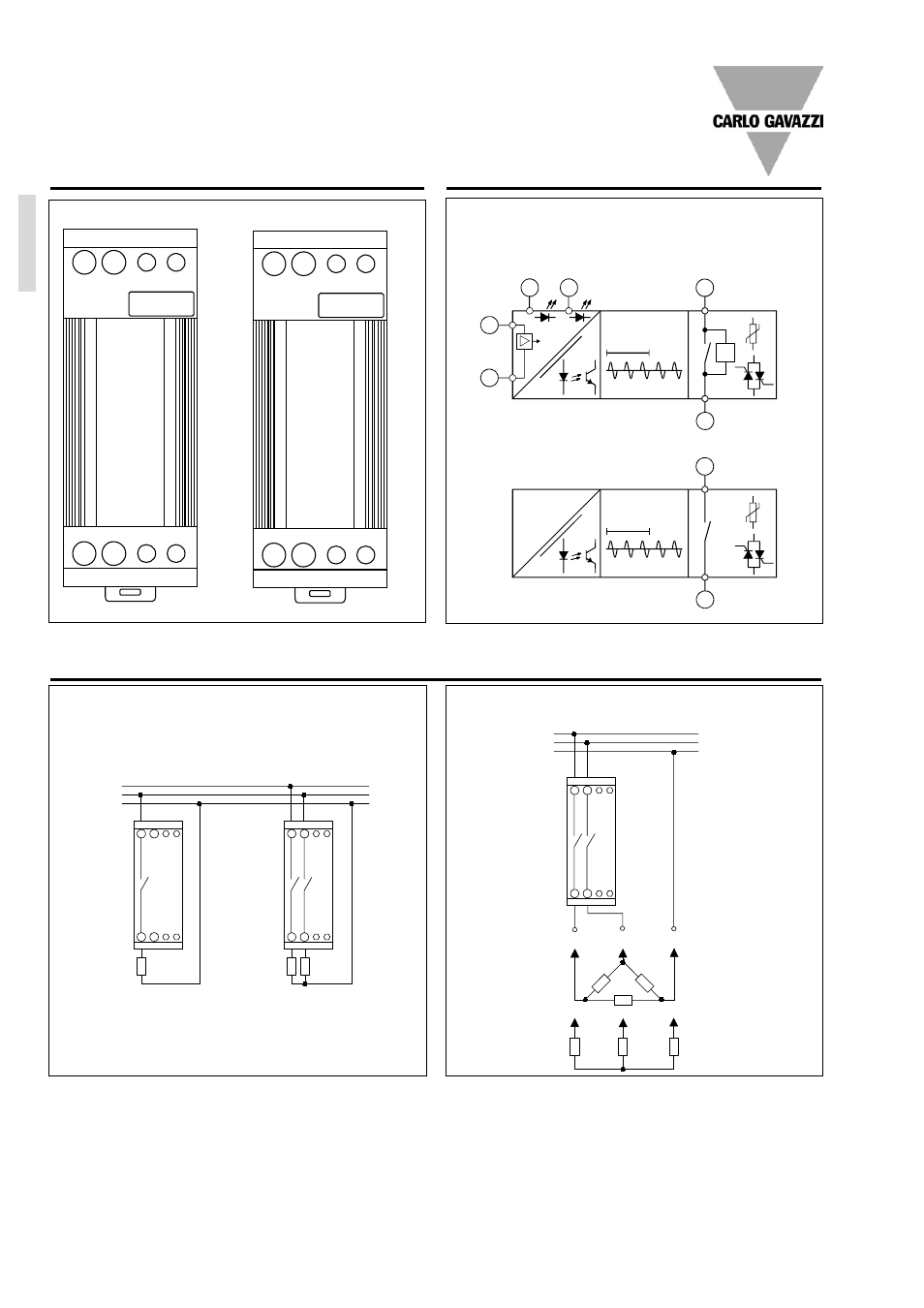
Functional Diagrams
Applications
Terminal Layout
1-pole RN..
2-pole RN..
L
1
A
1
A
2
A
1
L
2
L
1
T
1
A
3
T
1
A
4
A
3
T
2
RN 1F
A
2
A
4
Double pole relay in 3-phase application
Star and delta application (Economy Switching only)
L
1
L
2
L
3
2-pole current controlled input
Master
Slave (2-pole version)
Single and double pole relay application
Line-Neutral
L
1
L
2
N
VAC/VDC (A
3
, A
4
only used for voltage control)
control
signal
This manual is related to the following products: