Em-mpo/star3din installation instructions, Installation, Mount din rail – TREND EM-MPO_STAR3DIN User Manual
Page 2: Continued) fix on din rail, Do not apply power
2
EM-MPO/STAR3DIN Installation Instructions TG200770 Issue 1/B 07/04/05
EM-MPO/STAR3DIN
Installation Instructions
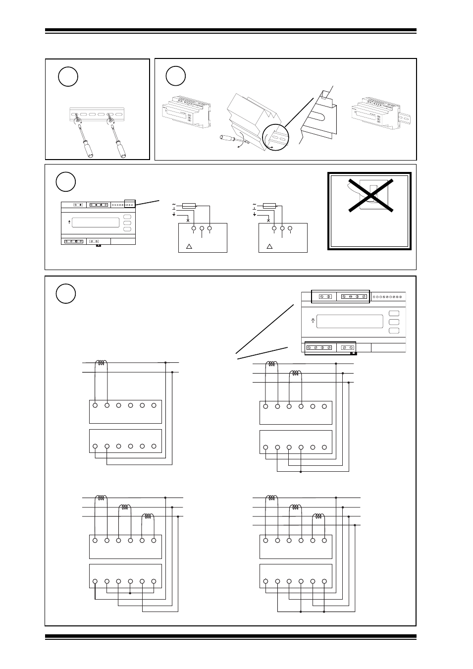
Connect Power to Meter
Connect Measurement Connections
Single part screw terminals, maximum cross section area cable 4 mm
2
Mount DIN Rail
2
INSTALLATION
(continued)
Fix on DIN Rail
3
4
DO NOT APPLY
POWER
0
I
230 Vac +15 % -20 %,
35 to 400 Hz, 4VA Supply
PAG
SEL
SET
STAR3 din
10Wh
MULTI PANEL METER
115 Vac +15 % -20 %,
35 to 400 Hz, 4VA Supply
Power Connector
5
if not using
ACC/STAR3DIN/PANELKIT
Panel Mounting Kit
(see step 7)
if not using ACC/STAR3DIN/PANELKIT Panel Mounting Kit
L
N
E
115 Vac
200 mA T
0V~
230V~
115V~
4VA~ 50/60Hz
POWER SUPPLY
!
L
N
E
230 Vac
100 mA T
0V~
230V~
115V~
4VA~ 50/60Hz
POWER SUPPLY
!
Note that this instrument does not require an earth connection
PAG
SEL
SET
STAR3 din
10Wh
MULTI PANEL METER
ABSOLUTE MAXIMUM CURRENT 7 A~
ABSOLUTE MAXIMUM VOLTAGE 600 V~
P1
P2
AL1
P1
P2
AL2
P1
P2
AL3
VL1
N
C U R R E N T I N P U T
V O L T A G E I N P U T
N
N
VL2
VL3
L
N
LO
AD
S1
S2
P1
P2
AL1
P1
P2
AL2
P1
P2
AL3
VL1
N
C U R R E N T I N P U T
V O L T A G E I N P U T
N
N
VL2
VL3
L1
L2
LO
AD
S1
S2
N
S1
S2
P1
P2
AL1
P1
P2
AL2
P1
P2
AL3
VL1
N
C U R R E N T I N P U T
V O L T A G E I N P U T
N
N
VL2
VL3
L1
L2
LO
AD
S1
S2
L3
S1
S2
S1
S2
P1
P2
AL1
P1
P2
AL2
P1
P2
AL3
VL1
N
C U R R E N T I N P U T
V O L T A G E I N P U T
N
N
VL2
VL3
L1
L2
LO
AD
S1
S2
L3
S1
S2
S1
S2
N
Single Phase with Neutral
2 Phase with Neutral
3 Phase without Neutral (Delta)
3 Phase with Neutral (Star)
Single part screw terminals, maximum
cross section area cable 2.5 mm
2
B
A
A
A
A
A
B
B
B
B