Em-mpo/star3 installation instructions, Installation, Continued) mount on panel – TREND EM-MPO_STAR3 User Manual
Page 2: Do not apply power, 91 mm, 91 mm 2 screws provided, A) remove clamp from meter
2
EM-MPO/STAR3 Installation Instructions TG20771 Issue 1/B 07/04/05
EM-MPO/STAR3
Installation Instructions
1
2
3
4
5 6 7 8
9 10 11
VOLTAGE INPUT
MAX 600V~
CAT 111
!
CURRENT INPUT
MAX 5A~
!
POWER SUPPLY
50/60Hz 6VA
!
VL3
VL2
VL1
N
AL3 AL2 AL1 COM 0
115 230V~
1
2
A
B
RS485
1
2
3
4
5
6
3
4
5
6
OUT
1A
OUT
1B
OUT
2A
OUT
2B
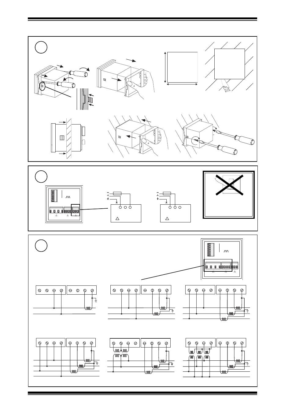
Connect Power to Meter
Connect Measurement Connections
Two part screw terminals, maximum cable cross section area 2.5 mm
2
INSTALLATION
(continued)
Mount on Panel
2
3
DO NOT APPLY
POWER
0
I
230 Vac +15 % -20 %,
35 to 400 Hz, 4VA Supply
1
2
3
4
5 6 7 8
9 10 11
VOLTAGE INPUT
MAX 600V~
CAT 111
!
CURRENT INPUT
MAX 5A~
!
POWER SUPPLY
50/60Hz 6VA
!
VL3
VL2
VL1
N
AL3 AL2 AL1 COM 0
115 230V~
1
2
A
B
RS485
1
2
3
4
5
6
3
4
5
6
OUT
1A
OUT
1B
OUT
2A
OUT
2B
115 Vac +15 % -20 %,
35 to 400 Hz, 4VA Supply
rear view
4
(a)
Remove clamp from Meter
L
N
E
115 Vac
200 mA T
0
230V~
115
4VA~ 50/60Hz
POWER SUPPLY
!
9
10
11
L
N
E
230 Vac
100 mA T
4VA~ 50/60Hz
POWER SUPPLY
!
0
230V~
115
9
10
11
Note that this instrument does not require an earth connection
ABSOLUTE MAXIMUM CURRENT 5 A~
ABSOLUTE MAXIMUM VOLTAGE 600 V~
1
2
3
4
VOLTAGE
L
N
LO
AD
S1
S2
5
6
7
8
CURRENT
VL3
VL2
VL1
N
AL3
AL2
AL1
COM
1
2
3
4
VOLTAGE
L1
L2
LO
AD
S1
S2
5
6
7
8
CURRENT
VL3
VL2
VL1
N
AL3
AL2
AL1
COM
N
S1
S2
1
2
3
4
VOLTAGE
L1
L2
LO
AD
S1
S2
5
6
7
8
CURRENT
VL3
VL2
VL1
N
AL3
AL2
AL1
COM
L3
S1
S2
S1
S2
1
2
3
4
VOLTAGE
L1
L2
LO
AD
S1
S2
5
6
7
8
CURRENT
VL3
VL2
VL1
N
AL3
AL2
AL1
COM
L3
S1
S2
S1
S2
N
Single Phase with Neutral
2 Phase with Neutral
3 Phase without Neutral (Delta)
3 Phase with Neutral (Star)
1
2
3
4
VOLTAGE
L1
L2
LO
AD
S1
S2
5
6
7
8
CURRENT
VL3
VL2
VL1
N
AL3
AL2
AL1
COM
L3
S1
S2
S1
S2
1
2
3
4
VOLTAGE
L1
L2
LO
AD
S1
S2
5
6
7
8
CURRENT
VL3
VL2
VL1
N
AL3
AL2
AL1
COM
L3
S1
S2
S1
S2
N
3 Phase without Neutral (Delta) using 2VTs
3 Phase with Neutral (Star) using 3CTs
Two part screw terminal, maximum cable cross
section 2.5 mm
2
(b)
Cut hole in Panel
(c)
Push meter through
hole
(d)
Push on clamp
(e)
Tighten clamp screws
91 mm
91 mm
2 screws
provided