Installation instructions tb/ts installation, If iq, If iql – TREND TB_TS User Manual
Page 3: Wire to controller, Assemble unit
TB/TS Thermistor Room Temperature Sensors Installation Instructions TG200604 Issue 1/E 14/02/07
3
Installation Instructions
TB/TS
INSTALLATION
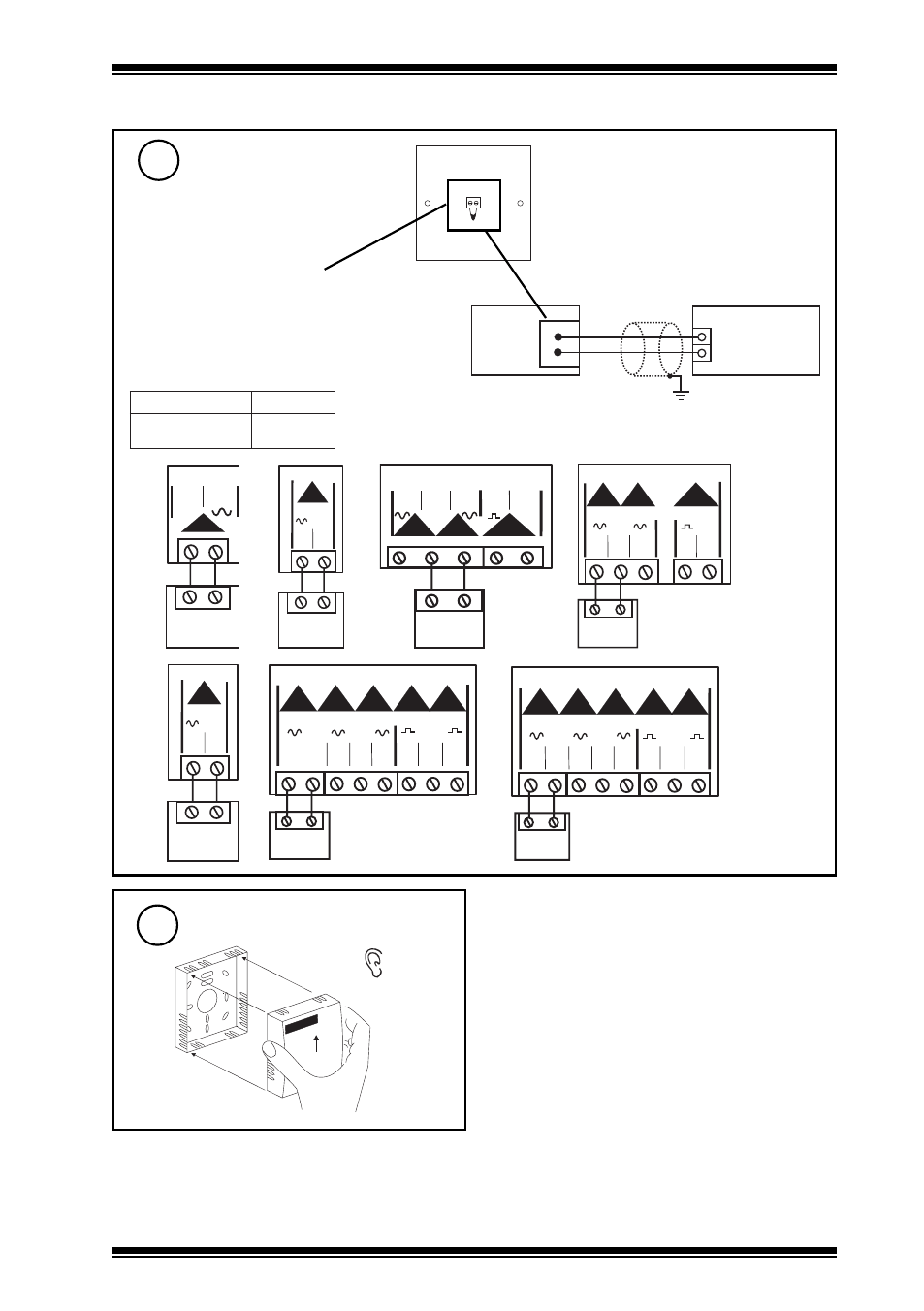
(continued)
Wire to controller
7
if IQ
Assemble unit
8
‘click’
0 V
Temperature
IN
SENSOR
IQ
TB/TS
linked for thermistor (T)
analogue input
COM (0V)
if IQL
TB/TS
C O M
9
10
1
I Q L 1 0 / 2 4 V A C
TB/TS
1 5 1 6
1
C O M
I Q L 1 0 / 2 3 0
TB/TS
9
1 0
1
1 1
1 2
1 3
3
C O M
C
2
I Q L 1 1 + / 2 4 V A C
TB/TS
C O M
1 5 1 6 1 7 1 8 1 9
1
2
3
C
I Q L 1 1 + / 2 3 0
TB/TS
2 1 2 2
1
C O M
I Q L 1 2 , 1 4
TB/TS
C O M
2 1 2 2 2 3 2 4 2 5 2 6 2 7 2 8
C O M
1
2
3
4
5
C
I Q L 1 3 + , 1 5 + , 1 6
Note that screened cable is not required for sensor
wiring to IQLs. If screened cable is used, the
screen must be terminated at the controller to its
supply cable earth.
polarity independent
L
Q
I
S
N
O
I
T
P
O
,
+
3
1
,
2
1
,
+
1
1
,
0
1
L
Q
I
7
1
,
6
1
,
+
5
1
,
4
1
S
T
/
B
T
Terminal size 0.5 to 2.5 mm
2
(14 to 20 AWG)
TB/TS
C O M
2 1 2 2 2 3 2 4 2 5 2 6 2 7 2 8
1
2
3
4
5
C
0 V
A I
1 0 V
I Q L 1 7