Wire to controller, Set up special iq strategies, Assemble unit – TREND TB_TS_KO, _OS, _KOS, _KOF, _KOSF User Manual
Page 3: Continued), Terminal size 0.5 to 2.5 mm, Click
TB/TS/KO, /OS, /KOS, /KOF, /KOSF Sensors Installation Instructions TG200606 Issue 1/D 14/02/07
3
Installation Instructions
TB/TS/KO, /OS, /KOS, /KOF, /KOSF
INSTALLATION
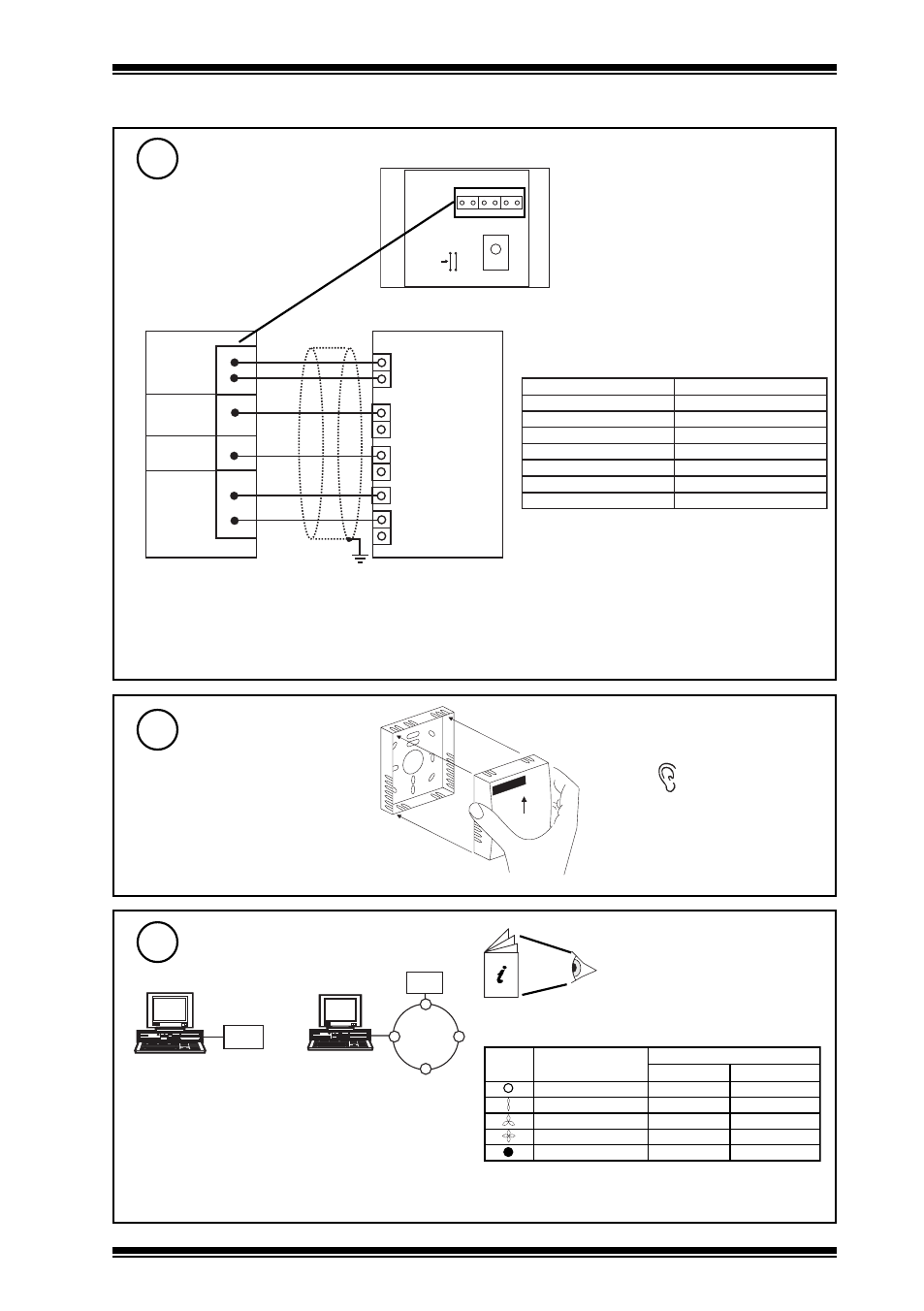
(continued)
Wire to controller
7
* For /KO or /KOF connect Status/Power to 10 Vdc or 24 Vdc; if using /KOS, /OS, /KOSF as /KO
or /KOF, the Status/Power input should be powered from 10 Vdc e.g. via dummy analogue output.
** For /OS option also connect knob.
*** Note that /KO, /OS, /KOS, /KOF, /KOSF cannot be used by IQ211 (although they can be used
by IQ212)
IQ Configuration Manual
90-1533
TB/TS Data Sheet TA200603
Set up special IQ strategies
9
I Q
I Q
or
For /KO, /OS, /KOS, /KOF, /KOSF special override
and status strategies.
For /KOF, /KOSF special strategy for fan speed
input on IQs
d
n
e
g
e
L
n
o
i
t
i
s
o
p
h
c
t
i
w
S
e
g
a
t
l
o
V
l
a
n
i
m
o
N
d
e
d
n
e
m
m
o
c
e
R
f
f
O
n
a
F
V
0
d
e
e
p
s
w
o
l
n
a
F
V
8
.
2
V
2
>
d
e
e
p
s
m
u
i
d
e
m
n
a
F
V
6
.
5
V
5
.
4
>
d
e
e
p
s
h
g
i
h
n
a
F
V
5
.
8
V
7
>
c
i
t
a
m
o
t
u
A
V
7
.
9
V
9
>
0 V
Temperature
Status/Power
Knob
+24 V
Fan
1
2
4
3
5
6
IN
OUT
0 V
IN
COM (0 V)
+24 V
IN
COM (0 V)
SENSOR
IQ
TB/TS
/K, /O
/S
/F
linked for thermistor (T)
analogue input
auxiliary supply
COM (0V)
analogue output
analogue input
see note ** below
analogue input
linked for thermistor (T)
linked for voltage (V)
linked for voltage (V)
1 2 3 4 5 6
LK1
LK2
Note that these options (TB/TS/
KO, /OS, /KOF, /KOSF) cannot be
used with IQLs; use options TB/TS,
TB/TS/K, /KE, or /KEF with IQLs.
N
O
I
T
P
O
S
L
A
N
I
M
R
E
T
T
C
E
N
N
O
C
S
T
/
B
T
2
,
1
K
/
S
T
/
B
T
3
,
2
,
1
*
*
*
O
K
/
S
T
/
B
T
*
4
,
3
,
2
,
1
*
*
*
S
O
/
S
T
/
B
T
4
,
*
*
3
,
2
,
1
*
*
*
S
O
K
/
S
T
/
B
T
4
,
3
,
2
,
1
*
*
*
F
O
K
/
S
T
/
B
T
6
,
5
,
*
4
,
3
,
2
,
1
*
*
*
F
S
O
K
/
S
T
/
B
T
6
,
5
,
4
,
3
,
2
,
1
Terminal size 0.5 to 2.5 mm
2
(14 to 20 AWG)
Note that the IQ recommended limits may need to be changed to suit mains supply voltage and auxiliary
supply loading, or a 24 Vdc regulated supply can be used.
Assemble unit
8
‘click’