T/fs data sheet installation – TREND T_FS User Manual
Page 2
2
T/FS Frost Protection Thermostat Data Sheet 91-2777 Issue 2 03/04/08
T/FS
Data Sheet
INSTALLATION
(1)
Mount frost stat in a reasonably clean location, free from
damp and condensation, using mounting bracket supplied
(120 mm, 4.72” fixing centres).
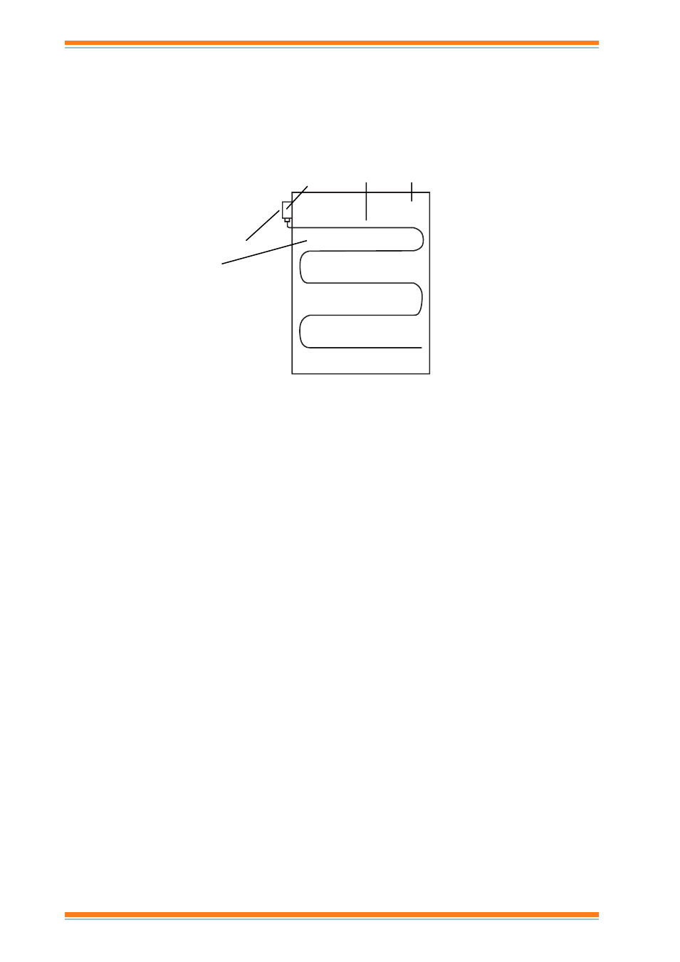
(2)
Install the complete length of the element so that it spans
the face area of the heat exchanger, as shown in the
diagram, so that it is exposed to all areas where low
temperatures are likely to be encountered.
Thermostat
Element
Duct
Typical Mounting Arrangement
Temperature of thermostat body
must be greater than
temperature setting point
The element is usually installed on the downstream side
of the heat exchanger and must be fixed in a vertical
plane.
The capillary has to be positioned with a large bend
radius, never less than 25 mm (~1”). It is recomended to
use the fixing clips (ACC/FC).
The T/FS has a 250 Vac, 15 A switching capacity. It should be
incorporated directly into the Air Handling Unit Control circuits to
protect heating and cooling exchanges and ductwork fabric
Alternatively, the T/FS can be used to provide an input to the IQ
system controller to initiate a frost protection control strategy.
If the capillary is damaged with a leak of gas the frost stat
simulates a low temperature and sets the switch accordingly.