Ht/d installation instructions, 2 installation, Insert cable through gland – TREND HT_D User Manual
Page 2: Wire to controller ht/d, Ht/d/2, Replace connector remove lid b a remove connector, Replace lid
2
HT/D Duct Humidity and Temperature Sensors Installation Instructions TG200988 Issue 1/A 30/01/08
HT/D
Installation Instructions
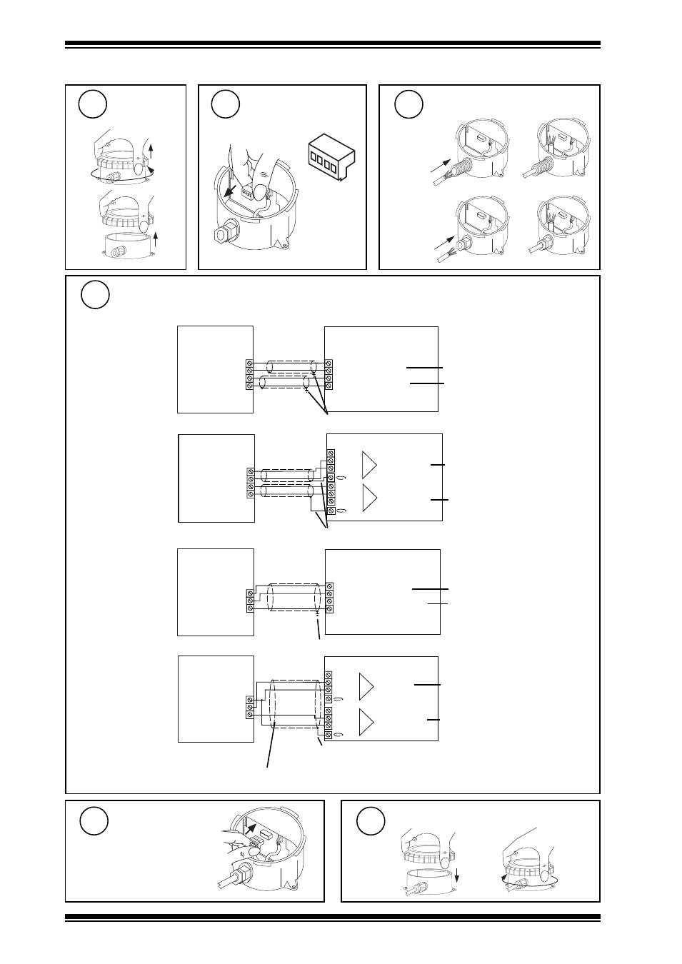
Insert cable through gland
either use
flexible
conduit
or use M16
cable gland
Wire to Controller
HT/D
I-P
I-N
TH
TH
IN
C
IN
C (+24V)
0 (0V)
N (in)
+ (+24V)
0 (0V)
N+1 (in)
+ (+24V)
N
N+1
I-P
I-N
TH
TH
IQ1 & IQ2
IQ3
terminate screens at IQ end
terminate screens at IQ end
temperature
humidity
} temperature
} humidity
linked for thermistor (T)
linked for current (I)
2 analog input channels
linked for thermistor (T)
linked for current (I)
HT/D/2%
C (+24V)
IN
C (+24V)
I-P
I1N
I2N
IN
0 (0V)
N (in)
+ (+24V)
0 (0V)
N+1 (in)
+ (+24V)
N
N+1
I-P
I1N
I2N
IQ1 & IQ2
IQ3
terminate screen at IQ end
terminate screen at IQ end
temperature
humidity
} temperature
} humidity
linked for current (I)
linked for current (I)
2 analog input channels
linked for current (I)
linked for current (I)
Note that when connecting to IQ3, in order to provide sufficient supply current to the sensor, the sensor I-P terminal must
be connected to both channels’ 24 V terminals.
Replace Connector
Remove lid
b
a
Remove Connector
2 INSTALLATION
(Continued)
4
5
6
7
8
Replace Lid
9