Installation instructions ws/s, /sd installation, Connect to iq, Configure iq – TREND WS_S, _SD User Manual
Page 3: Set up iq sensor type
WS/S, /SD Installation Instructions TG102613 Issue 2/C 08/01/07
3
Installation Instructions
WS/S, /SD
Installation
(continued)
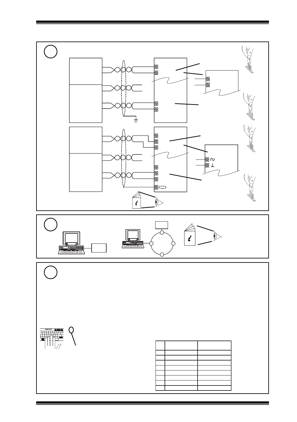
Connect to IQ
8
Configure IQ
9
G n ( 1 )
B k ( 2 )
W ( 3 )
B k ( 4 )
R ( 5 )
B k ( 6 )
2 4 V
I N
I N
0 V
I Q 1 , I Q 2 5 1
x
W S / S , / S D
W / S D
x
G n ( 1 )
B k ( 2 )
W ( 3 )
B k ( 4 )
R ( 5 )
B k ( 6 )
+ ( 2 4 V )
N ( i n )
0 ( 0 V )
+ ( 2 4 V )
N ( i n )
0 ( 0 V )
x
I Q 3
W S / S , / S D
W / S D
w i n d s p e e d
w i n d d i r e c t i o n
x
I Q
IQ Configuration
Manual 90-1533
I Q
or
IQ1, IQ2
IQ3
Input channel
linked for digital
input (D)
Input channel
linked for
thermistor (T)
T
D
Universal Input
channel linked for
digital input (D)
Input channel
linked for
thermistor (T)
T
D
Cable is 3 m (9’ 10”) long. If required
to extend:
WS/S, /SD Data Sheet TA102481
Set up IQ Sensor Type
(for wind speed sensor input)
10
It is recommended to use SET (Software Tool) for the setting of the sensor type module.
For all IQ2 series controllers with firmware version 2.1 or greater, or IQ3 series controllers,
the following SET Unique Sensor Reference should be used:
Wind Direction Therm
Alternatively used sensor scaling mode 5, characterise, and enter scaling manually as
defined in the table below:
For all other IQ controllers see WS/S, /SD Data Sheet TA102481.
tYpe Sensor digI/P Driver Function loGic Loop scHedule seQnc Analog
digBit Knob sWitch Time Zone Oss User addRess intcoN calarM reView Plot
calEndar
= ?
Yn
TYPE n
:=?
S=5 (characterise)
Y= , E= , U= , L= , P=
I1 to I3, O1 to O3=
X
Y
e
p
y
t
t
u
p
n
i
3
)
s
m
h
o
k
r
o
t
s
i
m
r
e
h
t
(
E
t
n
e
n
o
p
x
E
4
U
r
e
p
p
U
0
8
3
L
r
e
w
o
L
1
-
P
s
t
n
i
o
P
3
x
x
I
x
O
1
0
0
2
9
9
.
0
7
5
3
3
0
0
1
9
5
3
I N ( + 5 V )
C
I Q 2
( e x c l u d i n g I Q 2 5 1 )
I Q 3
Digital
input
channel