Installation instructions aq/d, Installation, Wait – TREND AQ_D User Manual
Page 3: Measure output, Set delay, Replace lid, Configure iq, Ab c, Set up iq sensor type
3
AQ/D Installation Instructions TG100525A Issue 3, 2/03/2009
Installation Instructions
AQ/D
V
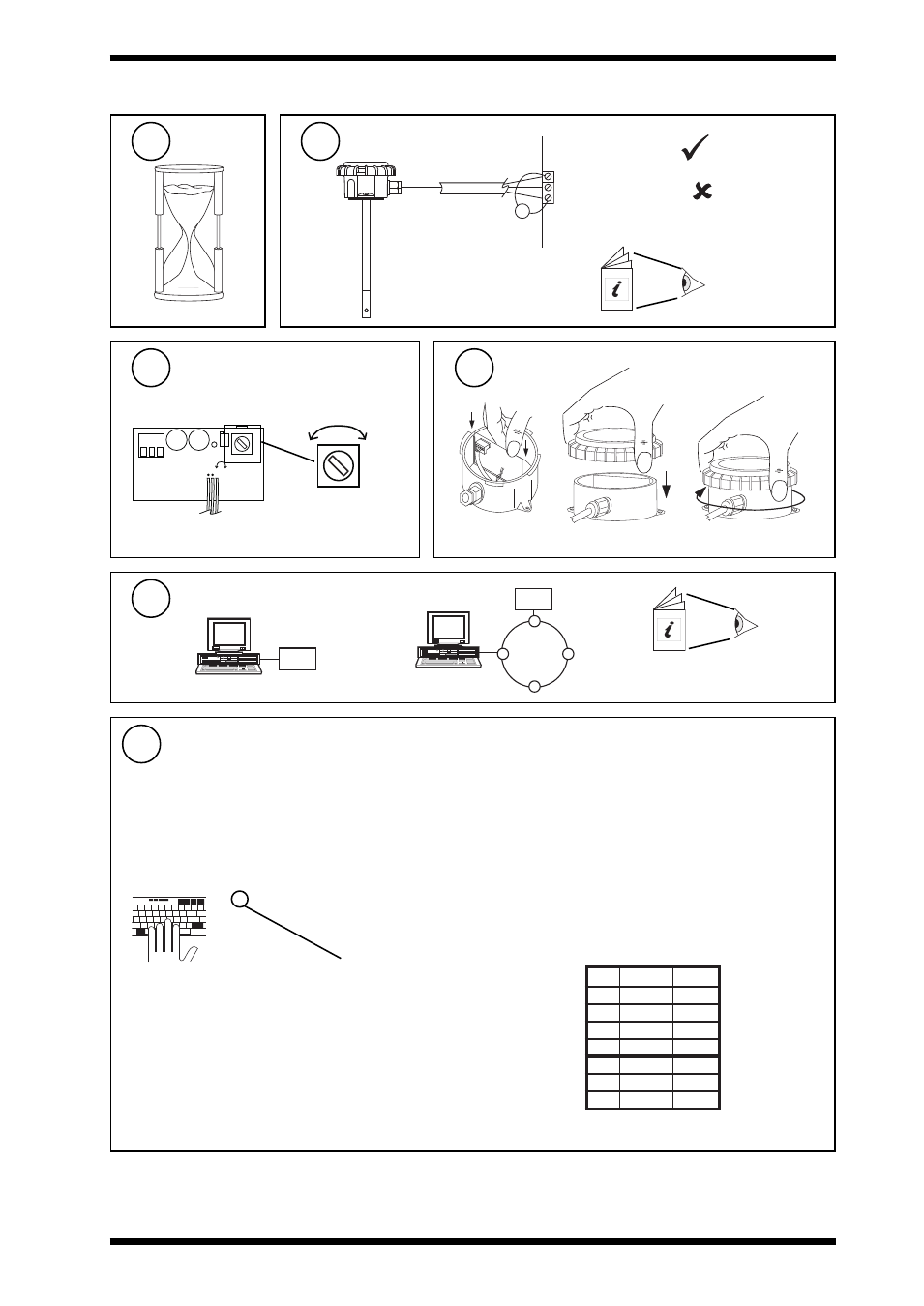
INSTALLATION
(Continued)
Wait
14
Measure Output
15
Set delay
16
Replace lid
17
LD1 VR1
Cal
OP
0V
24V
Run
VR2
-
+
DELAY
ADJUST
Configure IQ
18
30 mins
0V
IN
24V
V = 1 to 3 V
V < 1 or > 3V
- recalibrate
AQ/D Data Sheet
91-2747
-
+
(0 mins)
Min
(12 mins)
Max
Delay
a
b
c
IQ Configuration Manual 90-1533
I Q
I Q
or
tYpe Sensor digI/P Driver Function loGic Loop scHedule seQnc Analog
digBit Knob sWitch Time Zone Oss User addRess intcoN calarM reView Plot
calEndar
= ?
It is recommended to use SET (software tool) for the setting of the sensor type module. For all IQ2 series controllers with
firmware version 2.1 or greater, or IQ3 series controllers, the following SET Unique Sensor Reference should be used:
Air Quality V
If not using SET, use the following table for all IQ2 series controllers of firmware version 2.1 or greater or IQ3 controllers;
for all other IQ controllers see Sensor Scaling Reference Card TB100521A.
Air Quality (0-100%)
0 = good 100 = bad
Voltage
Yx
TYPE x
:
=?
S=5 (characterise )
Y=, E=, U=, L=, P=
I1 to I2=, O1 to O2=
Y
e
p
y
t
t
u
p
n
I
)
s
tl
o
v
(
0
E
t
n
e
n
o
p
x
E
3
U
r
e
p
p
U
0
0
1
L
r
e
w
o
L
0
P
s
t
n
i
o
P
2
x
x
I
x
O
1
0
0
2
0
1
0
0
1
Set up IQ Sensor type
19
Note that IP67 (NEMA6) rating is only achieved if the sensor is
correctly installed with cable or conduit connection fully tightened