Aq/d installation instructions, Installation – TREND AQ_D User Manual
Page 2
2
AQ/D Installation Instructions TG100525A Issue 3, 2/03/2009
AQ/D
Installation Instructions
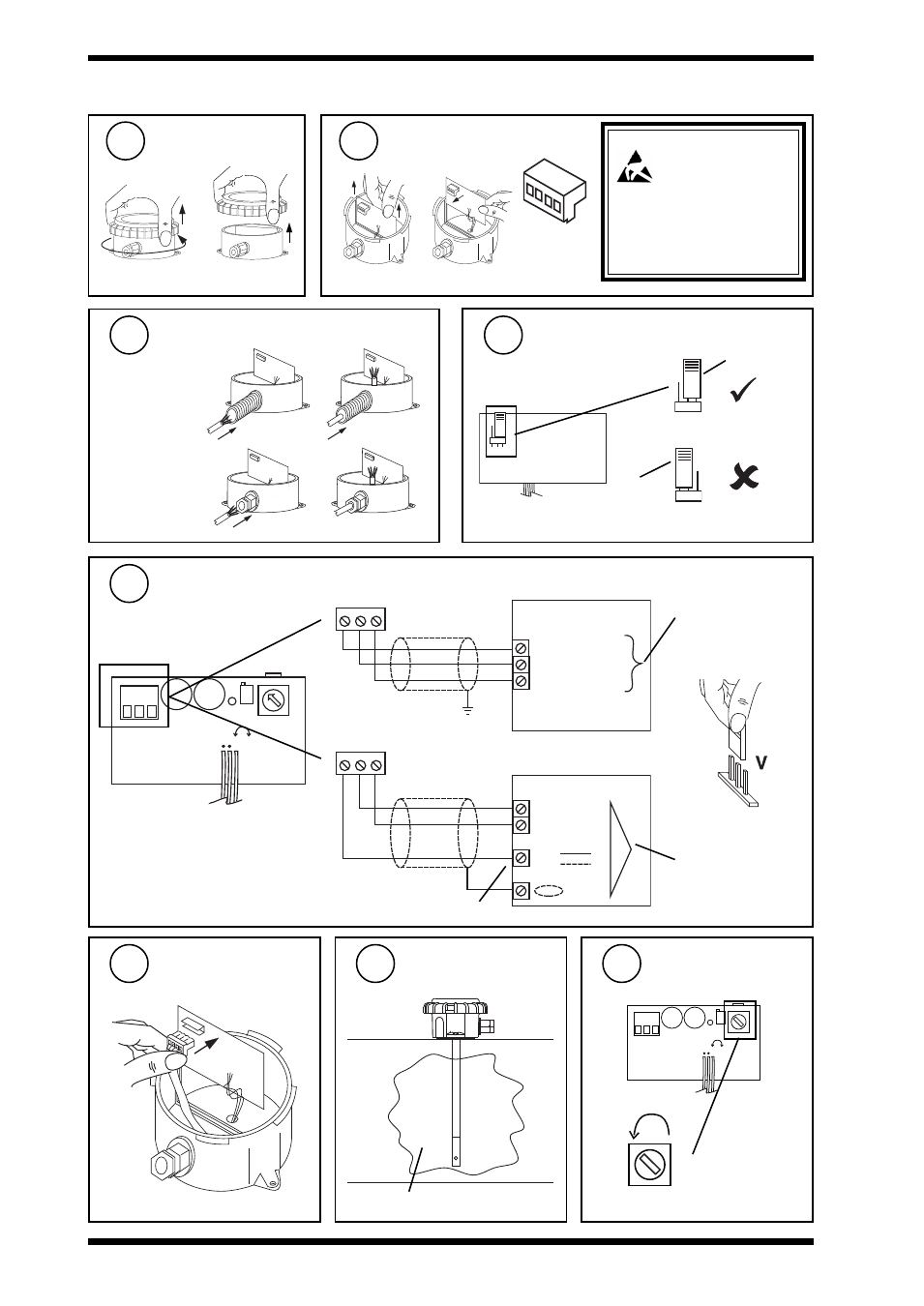
Insert cable through gland
either use
flexible conduit
or use
M20 cable gland
Check link is in ‘Run’ position
Cal
position
Run position
Remove lid
b
a
Remove Connector
Caution: This unit contains static
sensitive devices.
Suitable anti-static
precautions should be
taken throughtout the operation to
prevent damage to the units.
BS EN100015/1 Basic
Specification: protection of
electrostatic sensitive devices.
INSTALLATION
(Continued)
6
7
8
9
View of pcb from surface
mount side
10
L D 1 V R 1
C a l
O P
0 V
2 4 V
R u n
V R 2
-
+
D E L A Y
A D J U S T
-
+
24V 0V OP
24V 0V OP
IQ2
24V (AUX)
C (0V)
IN
IQ analogue input
channel linked for
voltage (V)
IQ3
0 (0V)
N (in)
24V
IQ analogue input
channel linked for
voltage (V)
N
Replace connector
11
Set minimum delay
13
Ensure clean
environment
12
LD1 VR1
Cal
OP
0V
24V
Run
VR2
-
+
DELAY
ADJUST
-
+
clean air
Delay
Note that sensor requires 96 mA from
24 V supply
Use auxiliary 24 Vdc output terminal as maximum current = 96 mA
Wire to Controller