Installation instructions aq/s, Installation, Remove backplate wait – TREND AQ_S User Manual
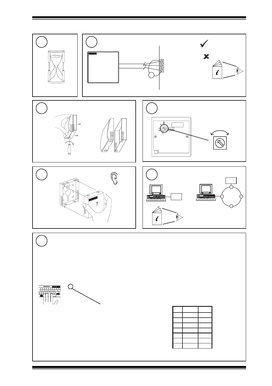
Page 3: Measure output, Set delay, Assemble unit, Configure iq, Set up iq sensor type
3
AQ/S Installation Instructions TG100526A Issue 2/A 05/06/06
Installation Instructions
AQ/S
V
0V
IN
24V
backplate
‘click’
IQ Configuration Manual 90-1533
IQ
IQ
or
a
b
30 mins
V = 1 to 3 V
V < 1 or > 3V
- recalibrate
AQ/S Data Sheet
91-2789
L D 1
C a l
N o r m a l
C a l
V R 1
M a x
O P
0 V
2 4 V
M i n
D e l a y
(0 mins)
Min
12 mins)
Max
Delay
Installation
(Continued)
Remove backplate
Wait
12
Measure output
13
14
Set delay
15
Assemble unit
16
Configure IQ
17
tYpe Sensor digI/P Driver Function loGic Loop scHedule seQnc Analog
digBit Knob sWitch Time Zone Oss User addRess intcoN calarM reView Plot
calEndar
= ?
It is recommended to use SET (software tool) for the setting of the sensor type module. For all IQ2 series controllers with
firmware version 2.1 or greater, or IQ3 series controllers, the following SET Unique Sensor Reference should be used:
Air Quality V
If not using SET, use the following table for all IQ2 series controllers of firmware version 2.1 or greater or IQ3 controllers;
for all other IQ controllers see Sensor Scaling Reference Card TB100521A.
Air Quality (0-100%)
0 = good 100 = bad
Voltage
Yx
TYPE x
:
=?
S=5 (characterise )
Y=, E=, U=, L=, P=
I1 to I2=, O1 to O2=
Y
e
p
y
t
t
u
p
n
I
)
s
t
l
o
v
(
0
E
t
n
e
n
o
p
x
E
3
U
r
e
p
p
U
0
0
1
L
r
e
w
o
L
0
P
s
t
n
i
o
P
2
x
x
I
x
O
1
0
0
2
0
1
0
0
1
Set up IQ Sensor type
18