Aq/s installation instructions, Installation, Mount backplate – TREND AQ_S User Manual
Page 2: Check link, Remove cutout, Route cable, Wire to controller, Set minimum delay, Loosely assemble unit, Clean air
2
AQ/S Installation Instructions TG100526A Issue 2/A 05/06/06
AQ/S
Installation Instructions
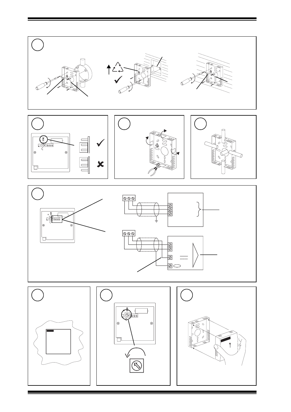
Mount backplate
4
Installation
(Continued)
Check link
5
wall
back box
(BESA)
35 mm (1.38”)
wall box
60 mm (2.36”)
35 mm (1.38”)
35 mm
(1.38”)
35 mm (1.38”)
FR
ABS
Remove cutout
6
as required
N o r m a l
C a l
L D 1
C a l
N o r m a l
C a l
V R 1
M a x
O P
0 V
2 4 V
M i n
D e l a y
N o r m a l
C a l
Route cable
7
Wire to Controller
8
L D 1
C a l
N o r m a l
C a l
V R 1
M a x
O P
0 V
2 4 V
M i n
D e l a y
Sensor
IQ1 & IQ2
Sensor
IQ3
0 (0V)
N (in)
24V
N
IQ analogue
input channel
linked for
voltage (V)
OP 0V 24V
24V (AUX)
C (0V)
IN
IQ analogue
input channel
linked for
voltage (V)
Note that sensor requires 96 mA
from 24 V supply
use auxiliary 24 Vdc output terminal as maximum current = 96 mA
L D 1
C a l
N o r m a l
C a l
V R 1
M a x
O P
0 V
2 4 V
M i n
D e l a y
M i n
D e l a y
backplate
Set minimum delay
10
Loosely assemble unit
11
Clean Air
9
Ensure clean
environment
OP 0V 24V