3 installation, Installation instructions 4dix/24vac, Wire 4dix to controller – TREND 4DiX_24Vac User Manual
Page 3: Connect 4dix to hva equipment, Configure controller, Continued), 4dix equipment power supply, 24 v loop or using external 24 vac/dc supply, Cable size 0.5 to 2.5 mm
O
I
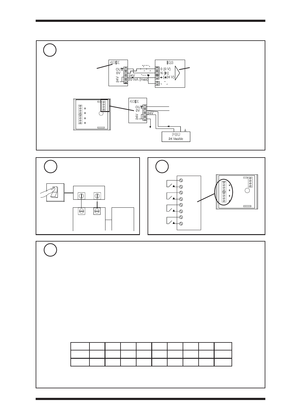
Wire 4DiX to controller
(continued)
3 installation
(continued)
Ensure Equipment input
power supply is switched
off
8
4DIX
Equipment
Power Supply
Input Power
Supply
4DIX
OUT
0V
24V
24V
PSU
24 Vac/dc
~+
-
24 V loop
or using external 24 Vac/dc supply
7
0V
OUT
24V
IN
C
A
IN
C
B
IN
C
C
IN
C
D
J5
J4
I
V
D
C
B
A
0V
24VDC
J2
J3
Note that external 24 V supply should be isolated or earthed
(grounded) to IQ earth (ground);
ensure correct polarity
connect 4DiX to HVa Equipment
9
0V
OUT
24V
IN
C
A
IN
C
B
IN
C
C
IN
C
D
J5
J4
I
V
D
C
B
A
0V
24VDC
J2
J3
Cable size 0.5 to 2.5 mm
2
(20 to 14 AWG), Cu only
HV
AC Equipment
volt free contacts
Configure controller
10
Mode
Y
E
U
L
P
I
1
I
2
O
1
O
2
I
2
3
270
-1
2
0
20
0
268.25
V
0
3
270
-1
2
0
10
0
268.25
4DIX
IQ3
OUT
0V
24V
N (in)
0 (0 V)
+ (+24 V)
24V
N
20 mA (max)
Connecting 4DIX in voltage mode to IQ3
Universal input channel
linked for voltage
4DIX in voltage mode
It is recommended to use SET (software tool) for configuring the controller. SET is supplied with 4DIX
strategy blocks for IQ1, IQ2, and IQ3 controllers; the strategy is described in the 4DIX data sheet.
If the SET strategy block is used it will set up both sensor scaling and strategy modules
(a) Sensor scaling:
For all IQ2 series controllers with firmware version 2.1 or greater, or IQ3 series controllers, the
appropriate SET Unique Sensor Reference from the following should be used:
Voltage (V) mode:
4DiXV
Current (I) mode:
4DiXI
If not using SET, use sensor type scaling mode 5, characterise, with the appropriate scaling from
the table below for all IQ2 series controllers of firmware version 2.1 or greater or IQ3 controllers; for
all other IQ controllers see Sensor Scaling Reference Card TB100521A.
Connect signal, 0 V, and screen to
controller as described above
(b) Strategy: The strategy must be set up to decode the digital status from the analogue input. The
SET 4DIX strategy blocks can be used as examples.
C
IN
C
IN
C
IN
C
IN
A
B
C
D
4DIX
Not suitable for counting inputs
4DIX/24VAC Four Digital Input Expander Module (24 Vac/dc) TG200651 Issue 3, 14/11/2008
3
installation instructions
4DiX/24Vac