3 installation, 4dix/24vac installation instructions, Mount on din rail – TREND 4DiX_24Vac User Manual
Page 2: Specify output signal, Ab c, Switch off iq, Wire 4dix to controller, Continued), Current i voltage v, Analogue input channel linked as table below
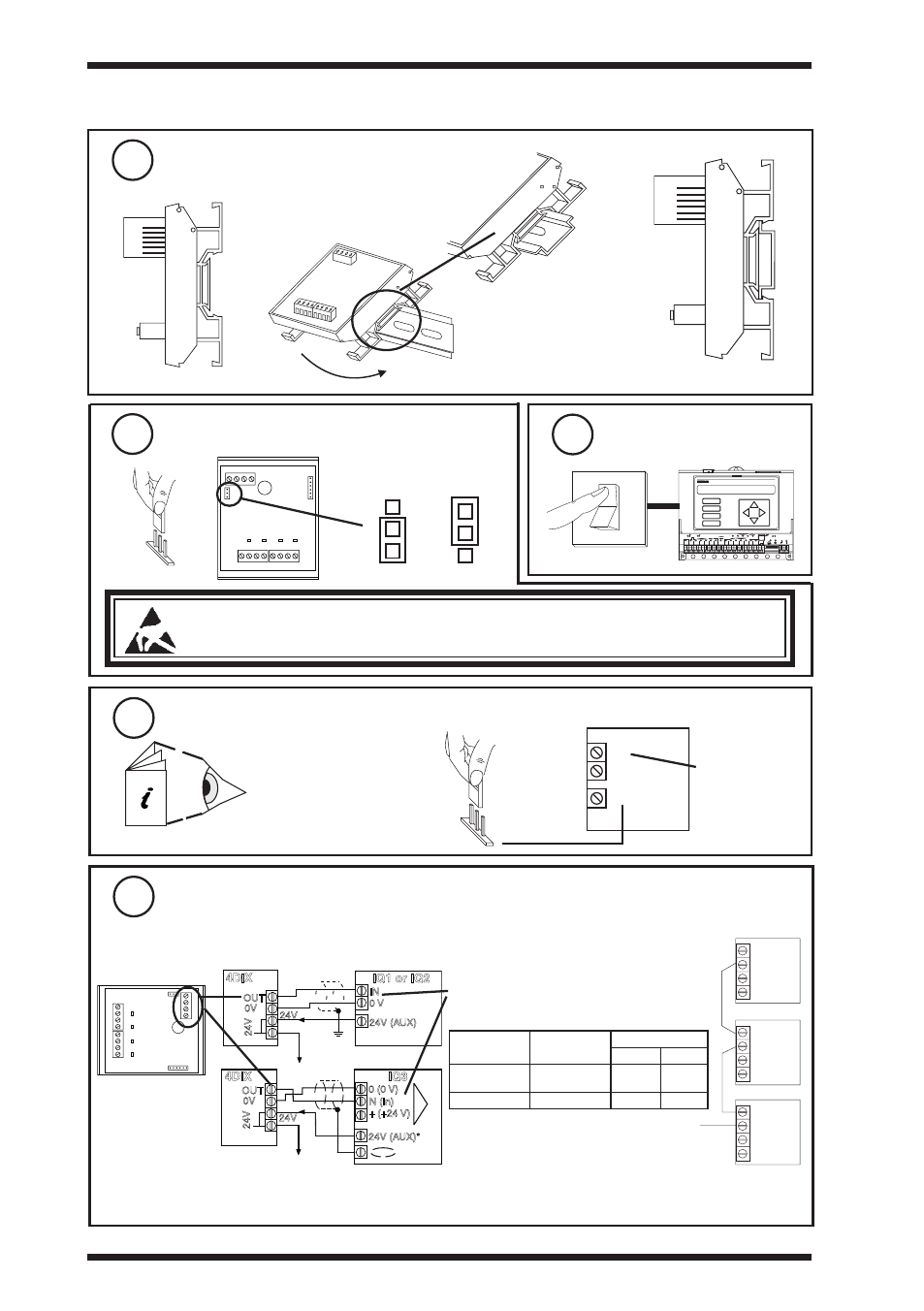
3 installation
(continued)
Mount on Din rail
3
specify output signal
4
a
b
c
0V
OUT
24V
IN
C
A
IN
C
B
IN
C
C
IN
C
D
J5
J4
I
V
D
C
B
A
0V
24VDC
J2
J3
V
J1
I
V
J1
I
Current
I
Voltage
V
switch off iQ
5
� � � � � � � � � � �
�
�
�
�
� �
� �
� �
� �
� � �
�
�
�
�
�
�
�
�
�
� �
� �
� �
� �
� �
� �
�
� � �
� �
� �
� �
� �
� �
�
�
IQ
caution: This unit contains static sensitive devices. Suitable anti-static precautions
should be taken throughout this operation to prevent damage to the unit.
BS EN100015/1 Basic Specification: protection of electrostatic sensitive devices.
set iQ input channel to analogue, and to match 4DiX output signal Mode
6
IN
C
24 V
IQ
IQ Controller
Installation Instructions
V or i
Wire 4DiX to controller
7
0V
OUT
24V
IN
C
A
IN
C
B
IN
C
C
IN
C
D
J5
J4
I
V
D
C
B
A
0V
24VDC
J2
J3
4DIX
XRM
XRM
24 V
analogue input
channel
either using IQ 24 Vdc auxiliary supply
4DIX
IQ1 or IQ2
OUT
0V
24V
24V
IN
0 V
24V (AUX)
Analogue input channel
linked as table below
4 DIX output mode
linking
IQ analogue input
channel linking
24 V current (max.)
24 Vac
24 Vdc
Current I
External powered
current I
x
90 mA
48 mA
Voltage V
Voltage V
48 mA
20 mA
Note that the controller’s 24 Vdc auxiliary supply should be used to supply the 4DIX, not the current input 24 V.
*However, the IQ3’s 24 Vdc terminal in an input channel terminal group is able to supply the 4DIX in voltage
mode (see below).
Cable size 0.5 to 2.5 mm
2
(20 to 14 AWG), Cu only
24 V loop
4DIX
IQ3
OUT
0V
24V
24V
+ (+24 V)
24V (AUX)*
N
N (in)
0 (0 V)
24 V loop
24 V loop
2
4DIX/24VAC Four Digital Input Expander Module (24 Vac/dc) TG200651 Issue 3, 14/11/2008
4DiX/24Vac
installation instructions