TREND 963 Web User Guide User Manual
Page 14
The 963 Client Displays
963 Web User Guide TC200685 Issue 4 15/01/2009
14
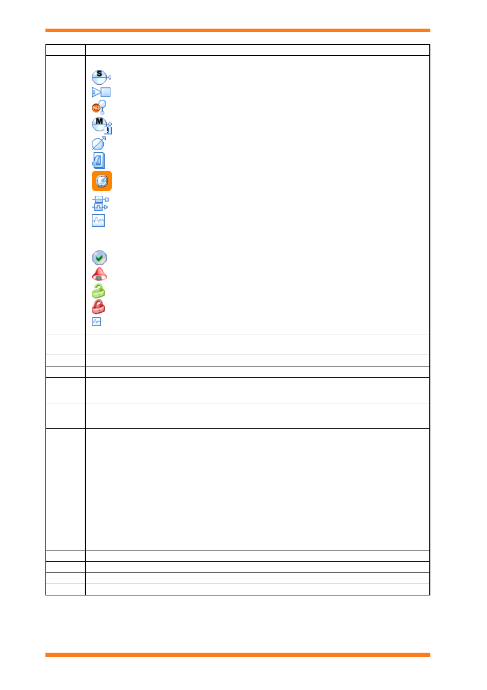
Column Description
Icon
Contains an icon that indicates the module type.
Sensor Modules
Digital Input Modules
Virtual Sensor Modules
Critical Alarm Modules
Knob Modules
Switch Modules
Time zone Modules
Analogue Driver Modules
Digital Driver Modules
Plot Modules
These icons may also overlayed with icons indicating the modules alarm state, and whether it can be
adjusted.
Module in alarm but alarm has been acknowledged
Module in alarm
Module value can be adjusted.
Module value cannot be adjusted.
There is a graph available for the module.
Label
The module label. For plot modules from pre IQ3 controllers will display the label of the module whose
value the plot module is recording.
Value
The current value of the module.
Units
The value’s engineering units.
Error
Description
A description of any error that exists for the value.
Alarm
Code
The alarm code for the alarm if the module is in an alarm condition.
Item
A code indicating the module type and number (e.g. S1 specifies Sensor module number 1)
S Sensor
Modules
I Digital
Input
Modules
W Switch
Modules
Z
Time zone Modules
K Knob
Modules
D
All Driver modules for IQ system sites, Analogue Driver Modules for BACnet sites
J
Digital Driver Modules for BACnet sites
X
Virtual Sensor Modules
P Plot
Module
M Critical
Alarm
Modules
LAN
The Lan number of the controller containing the module
OS
The network address of the controller containing the module
Tele
The phone number or IP address used to address the site containing the module.
Pin Level The PIN level required to adjust the value.