Aorm software package – Teledyne LeCroy AORM - Advanced Optical Recording Measurements User Manual
Page 117
AORM Software Package
923133 Rev A
ISSUED:
June 2013
115
trace; and it can be used for measurements of the clock frequency. If the JTA option is present, a
JitterTrack of Frequency of the extracted clock may give interesting insight into timing variation in
the input signal.
The only user-set parameter for clock extraction is the "PLL BW" setting on the "Equalizer and
PLL” dialog. The PLL Bandwidth is the unity gain intercept of the open-loop transfer function of
the PLL. The closed loop -3 dB frequency is approximately 1.274 time that. The loop filter meets
the specification shown in Annex H of the DVD Physical specifications (or Annex G of the DVD-R
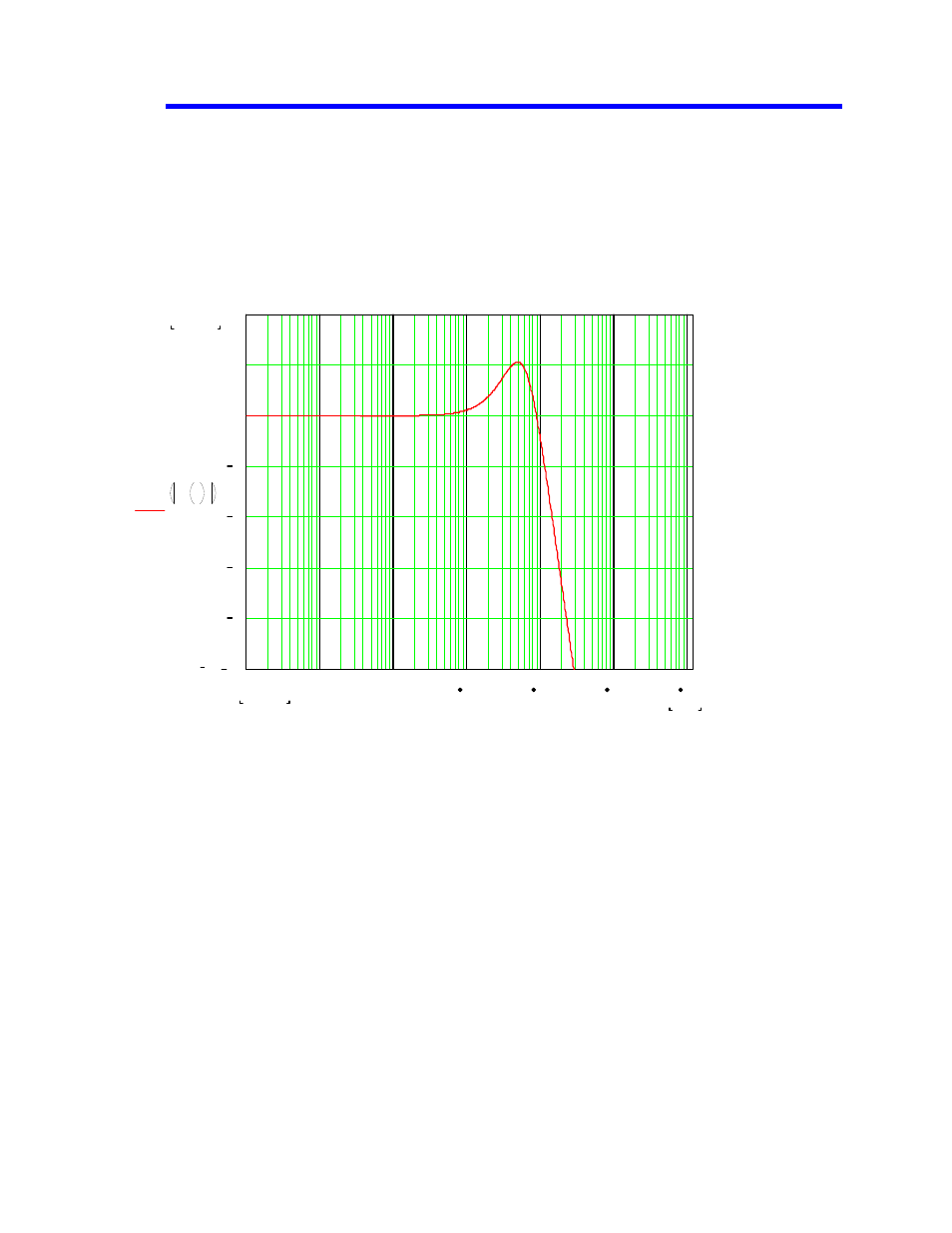
Physical specifications). For 1x DVD the PLL BW should be set to 9 kHz. In that case the
software PLL has this closed-loop response:
PLL closed-loop transfer function when "PLL BW" is set to 9 kHz.
The bandwidth of any PLL is a trade-off between jitter (phase noise) and desirable properties like
a wide locking range and fast tracking. The "lock range" is the maximum frequency step for which
the PLL can acquire lock without slipping a cycle. If we set up the VCO to start at other than the
correct frequency (which corresponds to a frequency step), the PLL must change frequency to
match the data. With PLL BW set to 9 kHz, the lock range is only about 25 kHz, slightly less than
0.1% of the expected clock frequency. The pull-in range is much broader but the pull-in time can
be quite long. If we start the VCO just 0.4% away from the correct frequency, it would take
hundreds of microseconds for the PLL to lock.
2.120975
10
20 log
H f
i
1 10
6
.
1.013911
f
i
1
10
100
1 10
3
1 10
4
1 10
5
1 10
6
10
8
6
4
2
0
2
4