System Sensor 5600 Series Heat Detectors User Manual
Page 3
D500-46-00
3
I56-2175-003R
likelihood of wiring errors. Improper connections
can prevent a system from responding properly in
the event of a fire.
The non-polarized screw terminals on the back of
the detector will accept 14–22 AWG wire. For best
system performance, all wiring should be installed
in separate grounded conduit; do not mix fire alarm
system wiring in the same conduit as any other
electrical wiring. Twisted pair may be used to pro-
vide additional protection against extraneous elec-
trical interference.
Wire connections are made by stripping approxi-
mately
1
⁄
4
˝ of the insulation from the end of the feed
wire, inserting it into the proper base terminal, and
tightening the screw to secure the wire in place.
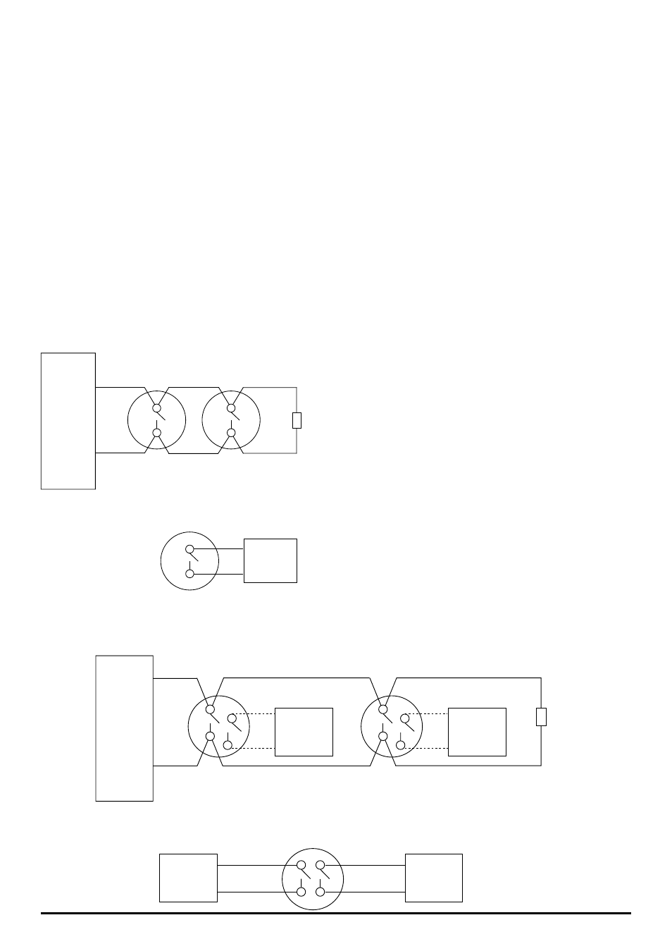
+
–
EOL
OR
Control
Panel
Auxiliary
Device
Auxiliary
Device
Auxiliary
Device
Auxiliary
Device
Auxiliary
Device
Control
Panel
+
–
OR
EOL
Figure 3. Wiring Diagram – Single Circuit Models:
Figure 4. Wiring Diagram – Dual Circuit Models:
Installation
Remove power from the alarm control unit or initi-
ating device circuits before installing detectors.
1. Detach the detector from the mounting bracket by
rotating the detector 1⁄4 turn counter-clockwise.
2. Orient the mounting bracket properly for either a
flush- or surface-mount installation (Figure 2).
3. Select the pair of mounting holes suitable for the
junction box, (Figure 1) and secure the bracket
to the box.
4. Connect the wires to the detector per Figure 3 or
Figure 4, as applicable.
5. Place the detector onto the mounting bracket by
rotating clockwise. The detector will lock into
place with a “click”.
6. After all detectors have been installed, apply
power to the alarm control unit.
7. Test each detector as described in Testing.
8. Reset all the detectors at the alarm control unit.
9. Notify the proper authorities that the system is
in operation.
S0239-00
S0240-00