System Sensor RTS-AOS User Manual
Page 2
SS-310-00
2
I56-3381-003
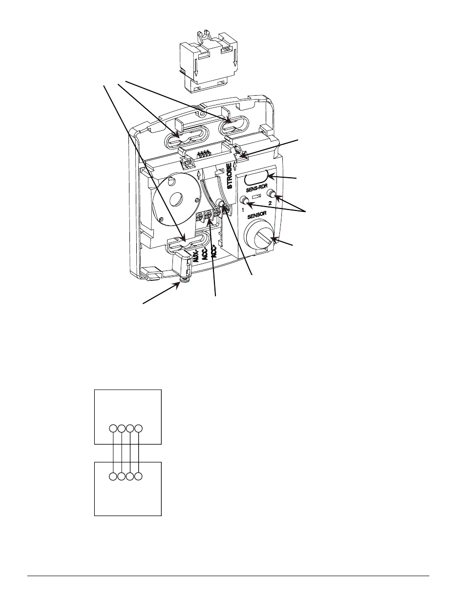
figUre 3: Wiring diagram
AUX
AUX
ACC
ACC
AUX
AUX
ACC
ACC
(-)
(-)
(-)
(-)
(+)
(+)
(+)
(+)
RTS2/RTS2-AOS
D4120/D4120W/D4P120
NOTE: If polarity of Acc. (+) and Acc. (—) are reversed,
an Amber LED on sensor 2 of the duct smoke detector
power board will exist indicating a trouble condition.
H0626-00
insTaLLaTiOn
installing the mounting plate
1. Secure the mounting plate to a single- or double-gang electrical box with
(2) mounting screws provided. Note: If mounting to a single-gang box, the
Add-On Strobe (AOS) must be removed prior to mounting. To remove the
AOS, squeeze opposing sides lightly next to arrows and slide vertically.
2. If applicable, install the AOS onto the mounting plate as shown in Figure 2.
Note, the RTS-AOS includes the AOS.
NOTE: installation per ULC S524-02
Temporal sounder
The RTS2 accessory provides the option of sounding a continuous or temporal
pattern. The RTS2 will default to sound in a temporal pattern. For a continu-
ous pattern, remove the jumper located just to the right of the “Strobe” text on
the mounting plate as shown in Figure 2.
Wiring
Wire the RTS2 as shown in Figure 3, for InnovairFlex 4-wire conventional duct
smoke detectors. Limit wire runs to 25 ohms or less per interconnecting wire.
nOTe:
1. If polarity of Acc. (+) and Acc. ( —) are reversed, an Amber LED on sensor
2 of the duct smoke detector power board will exist indicating a trouble
condition.
2. One RTS2 can be wired to only one InnovairFlex power board.
3. If Aux. (+) and Aux. (—) wires are reversed, the strobe and sounder will
not function.
installing the Outer Cover
1.Install the outer cover on the mounting plate by sliding the outer cover over
the upper tabs of the mounting plate as shown in Figures 4 and 5.
2.Tighten the outer cover mounting screw located at the bottom of the device.
Note: The mounting screw can be replaced with the provided tamper resistant
Torx screw, if desired.
SINGLE/DOUBLE-GANG
MOUNTING
AOS Add-On-Strobe
•SOLD SEPERATELY or
Included on RTS2-AOS
TEMPORAL JUMPER
LEDs
SELECTOR
KEY SWITCH
TEST/RESET
BUTTON
(4) TERMINALS
OUTER COVER
LOCKING SCREW
SENSITIVITY READER
LOCATION
(Remove for Continuous pattern)
H0624-00
figUre 2: