The limitations of directional sounders, Back box, as follows: a. use the two 8-32 × 1 – System Sensor PF24 Exitpoint User Manual
Page 4
D550-10-00
4
I56-2600-02R
©
2004 System Sensor
The directional sounder will not work without power. The directional sounder
gets its power from the fire/security panel monitoring the alarm system. If power
is cut off for any reason, the directional sounder will not provide the desired audio
warning.
The directional sounder may not be heard. The directional sounder may not be
heard if it is placed on a different floor from the person in hazard or if placed too far
away to be heard over the ambient noise such as traffic, air conditioners, machinery
or music appliances that may prevent alert persons from hearing the sounder. The
Sounder may not be heard by persons who are hearing impaired.
WARNING
The Limitations of Directional Sounders
System Sensor warrants its enclosed directional sounder to be free from defects in
materials and workmanship under normal use and service for a period of three years
from date of manufacture. System Sensor makes no other express warranty for this
directional sounder. No agent, representative, dealer, or employee of the Company
has the authority to increase or alter the obligations or limitations of this Warranty.
The Company’s obligation of this Warranty shall be limited to the repair or replace-
ment of any part of the directional sounder which is found to be defective in mate-
rials or workmanship under normal use and service during the three year period
commencing with the date of manufacture. After phoning System Sensor’s toll free
number 800-SENSOR2 (736-7672) for a Return Authorization number, send defective
units postage prepaid to: System Sensor, Returns Department, RA #__________, 3825
FCC Statement
NOTE: Directional Sounder has been tested and found to comply with the limits for a
Class A digital device pursuant to part 15 of the FCC Rules. These limits are designed
to provide reasonable protection against harmful interference when the equipment
is operated in a commercial environment. This equipment generates, uses, and can
radiate radio frequency energy and, if not installed and used in accordance with
the instruction manual, may cause harmful interference to radio communications.
Operation of this equipment in a residential area is likely to cause harmful interfer-
ence in which case the user will be required to correct the interference at his own
expense.
Three-Year Limited Warranty
Ohio Avenue, St. Charles, IL 60174. Please include a note describing the malfunc-
tion and suspected cause of failure. The Company shall not be obligated to repair or
replace units which are found to be defective because of damage, unreasonable use,
modifications, or alterations occurring after the date of manufacture. In no case shall
the Company be liable for any consequential or incidental damages for breach of this
or any other Warranty, expressed or implied whatsoever, even if the loss or damage
is caused by the Company’s negligence or fault. Some states do not allow the exclu-
sion or limitation of incidental or consequential damages, so the above limitation or
exclusion may not apply to you. This Warranty gives you specific legal rights, and you
may also have other rights which vary from state to state.
Please refer to insert for the Limitations of Fire Alarm Systems
Mechanical
Two screws are included for attaching the sounder to the
electrical junction box.
NOTE: If surface mounting is required, an extension ring
will be necessary to give proper depth for mount-
ing the sounder. The minimum depth required, in
the backbox/extension ring combination, is 2
1
/
4
″.
Any combination of 4″ × 4″ backbox and 4″ × 4″
extension ring that gives an interior depth of at
least 2
1
/
4
″ may be used.
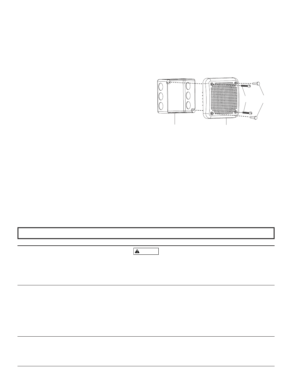
Mounting
See Figure 5. The sounder can be flush mounted on a
4″ Ч 4″ Ч 2
1
/
4
″ back box, as follows:
A. Use the two 8-32 × 1
3
/
4
″ screws (provided) to attach
the Sounder to the back box.
B. Plug the remaining two holes that will not be used
for attachment with the plugs provided.
Figure 5.
4" x 4" x 2-1/4"
BACKBOX
SPEAKER
SP201 SERIES
8-32
SCREWS
FILL
PLUGS
A0176-04