Table 4: power setting guide, Figure 2 – System Sensor PF24 Exitpoint User Manual
Page 3
D550-10-00
3
I56-2600-02R
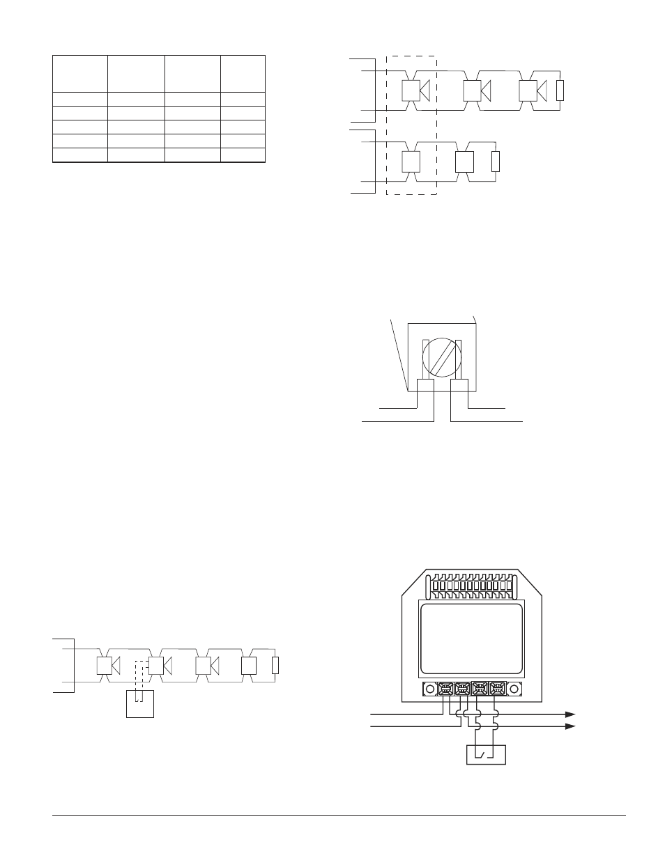
Table 4: Power Setting Guide
Switch
Position 1
Setting
Switch
Position 2
Setting
Switch
Position 3
Setting
Power
Setting
off
off
off
4 Watt
on
off
off
2 Watt
off
on
off
1 Watt
off
off
on
1
/
2
Watt
on
on
on
1
/
4
Watt
NOTE 1: Any other combinations of switch setting for
positions 1, 2, and 3 are invalid and should not
be used.
Consult the Directional Sound Applications Guide for
information regarding the appropriate power, speed, and
additional tone selections.
Electrical
Connect the Sounder as shown in Figure 1 for 2-wire appli-
cations. Connect the sounder as shown in Figure 2 for 4-
wire applications.
4-wire notification appliance circuits are circuits that use a
separate power supply and pair of wires for sounder and
strobe circuits. Some types of notification circuits may provide
coded signals to the sounders by pulsing the power supply on
and off in specific patterns such as the temporal 3 evacuation
signal. The directional sounders should not be connected to
4-wire sounder circuit power supplies where coded signals are
used to pulse the sounders. Directional sounders may be used
in conjunction with sync modules such as the System Sensor
MDL or syncable power supplies. The sounder is compatible
with syncable power supplies using any of the following syn-
cronization protocols; wheelock, gentex, and faraday.
All wiring must be installed in compliance with the
National Electrical Code (NEC) and applicable local codes
as well as special requirements of the authority having
jurisdiction.
Figure 1.
TWO WIRE SYSTEM
ANY MIX OF MODELS
OPTIONAL DISABLE CONTACT
NOTE: SWITCH POSITION 4 SETS
THIS INPUT TO EITHER
ACTIVE OPEN OR ACTIVE CLOSED.
HORN
(+)
(–)
(+)
(–)
E
O
L
(+)
(–)
(+)
(–)
(+)
(–)
HORN/STROBE
DIRECTIONAL
SOUNDER
STROBE ONLY
A0338-00
Figure 2.
FOUR WIRE SYSTEM:
ANY MIX OF HORNS
AND SOUNDERS OR
HORN/STROBES
HORN/STROBE
(+)
(–)
(+)
(–)
E
O
L
(+)
(–)
(+)
(–)
HORN
DIRECTIONAL
SOUNDER
FOUR WIRE SYSTEM:
ANY MIX OF STROBES
AND HORN/STROBES
STROBE
POWER
SUPPLY
SOUNDER
POWER
SUPPLY
(+)
(–)
(+)
(–)
E
O
L
(+)
(–)
STROBE
A0344-00
NOTE: DO NOT loop electrical wiring under terminal
screws. Wires connecting the device to the control
panel must be broken at the device terminal con-
nection in order to maintain electrical supervision.
See Figure 3.
Figure 3.
BREAK WIRE AS SHOWN FOR
SUPERVISION OF CONNECTION.
DO NOT ALLOW STRIPPED WIRE
LEADS TO EXTEND BEYOND SWITCH
HOUSING. DO NOT LOOP WIRES.
A0337-00
The sounder has a set of input terminals to provide addi-
tional control of the sound output of the directional sounder.
These terminals can be connected to the dry relay contacts
of control devices such as heat sensors or control modules.
When the input is active it will disable the sound output
of the Sounder. Connect the disable function as shown in
Figure 4. Refer to Table 3 for function switch settings.
Figure 4.
+ VDC
TO NEXT DEVICE
OR EOL
OPTIONAL DISABLE CONTACT
– VDC
A0339-00