Watt setting – System Sensor PF24 Exitpoint User Manual
Page 2
D550-10-00
2
I56-2600-02R
The same number of devices using 12 AWG wire will
produce only a 2 volt drop. The same number of devices
using 18 AWG wire will produce an 8 volt drop. Consult
your panel manufacturer’s specifications, as well as the
sounder’s operating voltage to determine the acceptable
voltage drop.
NOTE: If class “A” wiring is installed the wire length may
be up to 4 times the single wire length in this cal-
culation.
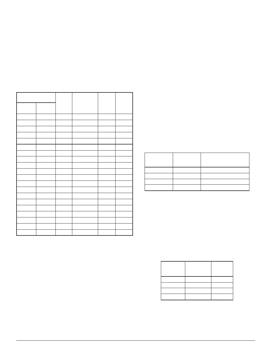
Table 1: Current Draw Measurements and
Sound Output Guide
Speed Selection
Power
Setting
Maximum DC
Operating
Current
(mA RMS)
(16 to 33V)
Audibility
(dBA)
(16 to
33V)
Note 1
Audibility
(dBA)
(16 to
33V)
Note 2
Speed
Switch
Selection
FAST (exit)
10
4 Watt
225
85
78
FAST (exit)
10
2 Watt
114
82
76
FAST (exit)
10
1 Watt
75
79
73
FAST (exit)
10
1
/
2
Watt
62
76
69
FAST (exit)
10
1
/
4
Watt
49
73
66
MED1
9
4 Watt
221
85
77
MED1
9
2 Watt
112
82
74
MED1
9
1 Watt
74
79
71
MED1
9
1
/
2
Watt
61
76
68
MED1
9
1
/
4
Watt
48
73
65
MED2
8
4 Watt
203
85
78
MED2
8
2 Watt
103
82
75
MED2
8
1 Watt
68
79
73
MED2
8
1
/
2
Watt
56
76
69
MED2
8
1
/
4
Watt
44
73
66
SLOW
7
4 Watt
189
85
76
SLOW
7
2 Watt
96
82
73
SLOW
7
1 Watt
63
79
70
SLOW
7
1
/
2
Watt
52
76
67
SLOW
7
1
/
4
Watt
41
73
64
NOTE 1: Sound output measured in anechoic room at 10 feet.
NOTE 2: Sound output measured in a reverberant room at 10 feet.
Installation
Consult the Directional Sound Applications Guide for
information regarding the appropriate mounting locations
of directional sounders.
Switch Settings
Selections are made via DIP switches on the back of
the sounder. Switch positions 7-10 are used to select the
pulse pattern of the sounder. Switch 10 is used to mark
the perimeter exit locations (fastest pulse). The remaining
settings are used for egress routing to the perimeter exit.
The egress route would originate with the “slow” (switch
7) tone and follow “medium 2” (switch 8) to “medium 1”
(switch 9) and finally the exit point “fast” (switch 10). If
more than one switch is selected the sounder will default
to the fastest selected setting.
Switch positions 5 and 6 are used to select additional
tone pulses that can be inserted in between bursts of the
directional sound pulses. The additional tone pulse will
be inserted on every 6th directional sound pulse. These
switches should be used when the sounder will be placed
near a stairway to guide a building occupant up or down
the stairs. Switch setting 5 inserts a down sweep indicat-
ing the presence of a downward stairway. Switch setting 6
inserts an up sweep indicating the presence of an upward
stairway. If switch positions 5 and 6 are both set to “on”
this will insert a special tone for use near areas of refuge.
The area of refuge tone should be used if the directional
sounder is marking an area of refuge. This tone provides
a distinct signal indicating that the sounder is not mark-
ing an exit. If both switches are set to “off” the sounder
will default to no additional tones. In this case only the
directional sound pulses will be heard. See Table 2 for tone
selection options.
Table 2: Additional Tone Selection Guide
Switch
Position 5
Setting
Switch
Position 6
Setting
Sound Output
on
on
Refuge
on
off
DOWN Stairs
off
on
UP Stairs
off
off
no tones
Switch setting 4 enables a directional sound device to
become disabled when used in conjunction with devices
with dry contacts such as heat sensors or control modules.
The sounder has a set of input terminals that can be con-
figured for an “active open” or “active closed” state. When
the switch is in the “on” position, the sounder is “on”
when the disable connection is closed. When the switch is
in the “off” position, the sounder is “on” when the disable
connection is open. See Table 3 for operation modes.
Table 3: Enable/Disable Function Logic Table
Switch
Position 4
Setting
Terminals 3
& 4
Sound
Output
on
open
disabled
on
closed
enabled
off
open
enabled
off
closed
disabled
There are five different power settings for the sound output
pressure. Switch settings 1, 2, and 3 set the power setting
for the sounder. Switch 1 selects the 2 watt setting, switch 2
selects the 1 watt setting, switch 3 selects the
1
/
2
watt setting.
If all three switches are “off” this selects the 4 watt setting and
if all three switches are “on” this selects the
1
/
4
watt setting.