Steelcraft Automotive 133800 RUNNING BOARD User Manual
Steelcraft Automotive For the car
VIEWPOINT ALUMINUM RUNNING BOARD
2010-12 TOYOTA 4RUNNER
SR5 AND LIMITED MODELS (EXCL TRAIL EDITION)
Page 1 of 3
9/17/12 Rev1(DP)
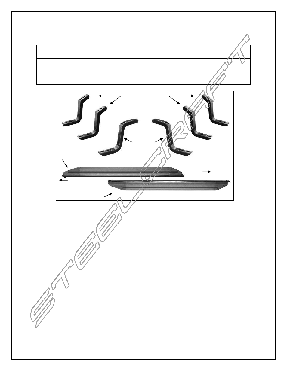
PARTS LIST:
1 Driver/Left Running Board
12 8mm x 22mm OD x 2mm Flat Washers
1 Passenger/Right Running Board
12 6mm x
20mm “T” bolts
2 Front Mounting Brackets
12 6mm Lock Washers
4 Center & Rear Mounting Brackets
12 6mm x 22mm OD x 2mm Flat Washers
12 8-1.25mm x 30mm Hex Bolts
12 6mm Hex Nuts
12 8mm Lock Washers
PROCEDURE:
1. REMOVE CONTENTS FROM BOX. VERIFY ALL PARTS ARE PRESENT. READ INSTRUCTIONS
CAREFULLY BEFORE STARTING INSTALLATION.
2. Starting on the passenger side of the vehicle, remove the existing (2) factory bolts located by the front
tire opening securing the factory rocker panel bracket to the vehicle, (Figure 1). Select (1) Front
Mounting Bracket. Hold the Front Bracket over the rocker panel bracket and line up the (2) mounting
holes. Secure the brackets to the vehicle using the included longer (2) 8mm x 30mm Hex Bolts, (2)
8mm Lock Washers and (2) 8mm Flat Washers, (Figure 2). Do not tighten hardware at this time.
3. The center and rear brackets are identical. Select (1) Center/Rear Bracket and repeat the procedure as
described in Step 2 to install it in the center mounting location, (Figure 3). NOTE: Install (1) mounting
bracket at a time. Do not tighten hardware at this time.
4. Repeat Step 3 for rear Mounting Bracket installation.
5. Carefully unwrap the Running Board and select passenger side Board. Select (6) 6mm T-Bolts. Insert
(3) T-Bolts into each channel on the bottom of the Running Board, (Figure 4). Slide the T-Bolts forward
or back to line up with the (3) previously installed Mounting Brackets, (Figure 5). Hold the Running
Board up to the vehicle at a slight angle and gently push it into position against the rocker panel,
(Figure 6). Line up the T-Bolts with the slots in the Brackets.
6. Attach the Running Board to the Mounting Brackets with the included (6) 6mm Flat Washers, (6) 6mm
Lock Washers and (6) 6mm Hex Nuts, (Figures 7 & 8). Do not tighten at this time.
7. Level and adjust the Sidebar as desired and tighten all hardware. Repeat Steps 2
– 6 for the driver side
Running Board installation.
8. Do periodic inspections to the installation to make sure that all hardware is secure and tight.
(4) Center & Rear
Mounting Brackets
Passenger/Right Side Running Board
Driver/Left Side Running Board
(2) Front
Mounting
Brackets
FIG. 1
(2) 8mm x 30mm Hex Bolts
(2) 8mm Lock Washers
(2) 8mm Flat Washers
13mm socket required
FIG. 2
FIG. 4
Gently push into position
Front
Rear
Longer angle to front