Wiring accessories to the control board, Additional features – LiftMaster CSW24V High-Cycle Commercial DC Swing Gate Operator User Manual
Page 35
33
ADDITIONAL FEATURES
A
Open Input (&
common)
(3-Button Control
Station, 4 terminals
total)
Open command - opens a closed gate.
Hard open (maintained switch overrides external
safeties and resets alarm condition)
If maintained, pauses Timer-to-Close at OPEN limit.
Opens a closing gate and holds open an open gate
(within line-of-sight).
B
Close Input (&
common)
(3-Button Control
Station, 4 terminals
total)
Close command - closes an open gate.
Hard close (maintained switch overrides external
safeties and resets alarm condition within line-of-sight)
C
Stop Input (& common)
(3-Button Control
Station, 4 terminals
total)
Stop command - stops a moving gate.
Hard stop (maintained switch overrides Open and Close
commands and resets alarm condition)
If maintained, pauses Timer-to-Close at OPEN limit.
Overrides Open and Close commands (within line-of-
sight).
D
Fire Dept Open Input
(2 terminals)
Acts as hard open.
Maintained input overrides (ignores) external safeties
(photoelectric sensor and edge), pauses Timer-to-Close
momentary input logic as single button control and
safeties remain active, re-enables Timer-to-Close.
E
Exit Loop Input
(2 terminals)
Open command - opens a closed gate.
Soft open (maintained switch does not override
external safeties and does not reset alarm condition)
If maintained, pauses Timer-to-Close at OPEN limit.
Opens a closing gate and holds open an open gate.
F
Shadow Loop Input
(2 terminals)
Loop detector connection when loop is positioned under
gate.
- Holds open gate at open limit
- Disregarded during gate motion
- Pauses Timer-to-Close at OPEN limit
G
CLOSE EYES/Interrupt
Loop Input
(2 terminals)
CLOSE EYES/Interrupt Loop detector connection when
loop is along the side of the gate.
- Holds open gate at open limit
- Stops and reverses a closing gate to open limit
- Pauses Timer-to-Close at OPEN limit
Close Direction Photoelectric Sensors, IR, or Infra-red
detector wired to CLOSE EYES Input, disregarded during
gate opening.
Pulsed Photoelectric Sensors = monitored device putting
out a pulse train when unblocked.
Photoelectric Sensors, IR, Infra-red detector, normally
open contact, contact opens fully with obstruction.
H
Close Edge
(2 terminals)
Close Direction Edge Sensor to Close Safety Input,
disregarded during gate opening
I
Open Eyes/Edge
(2 terminals)
Open Direction Photoelectric Sensors, IR, Infra-red
detector wired or Edge Sensor to Close Entrapments
Input, disregarded during gate closing,
Pulsed Photoelectric Sensors = monitored device putting
out a pulse train when unblocked.
Photoelectric Sensors, IR, Infra-red detector, edge
sensor = normally open contact, contact reverses for 2
seconds with obstruction.
J
Comm Link
(2 terminals)
Commercial Link (two wires) - connects two operators
together (primary-secondary wired connection)
K
Lock Outputs: Maglock
(2 terminals, N.C. and
COM)
Relay contact output, Normally - closed (N.C.) output
for maglocks
Relay activates prior to motor activation and during
motor run. Relay is off when motor is off.
L
Solenoid Lock &
Common
(2 terminals, N.O. and
COM)
Normally - open (N.O.) output for solenoid locks
Relay activates prior to motor activation and during
motor run. Relay is off when motor is off.
M
Accessory Power Out
Switched,
(2 terminals)
Switched ON with gate motion (stays on 5 seconds after
motion)
N
Accessory Power Out
Un-switched,
(2 terminals)
24 Vdc voltage out to power accessories, always ON
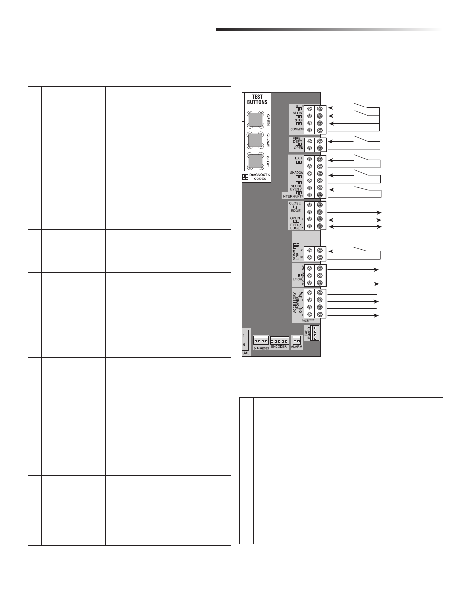
Open
Close
Stop
Com
Com
Com
Com
Interrupt
Close Edge (+)
Fire Dept
Exit
Shadow
Close Eyes
Close Edge (-)
Comm Link Data A
Comm Link Data B
Open Eyes/Edge (+)
Open Eyes/Edge (-)
Lock N.C. (Maglock)
Com
Lock N.O. (Solenoid)
Com (-)
AccPower +24 Vdc
Com (-)
AccPower +24 Vdc
3 Button
Station
Fire Dept.
Exit Loop
Shadow Loop
Close Eyes/
Interrupt Loop
Comm Link
Close Edge
Open Eyes/Edge
Mag and
Solenoid Lock
A
B
C
D
E
F
G
H
I
J
K
L
M
N
Acc. Power
(right side of control board)
WIRING ACCESSORIES TO THE CONTROL BOARD
WIRING ACCESSORIES TO THE CONTROL BOARD
Refer to the chart below and the corresponding image for a description of the control
board inputs.