Wiring, Power wiring continued – LiftMaster CSW24V High-Cycle Commercial DC Swing Gate Operator User Manual
Page 23
21
POWER WIRING
WIRING
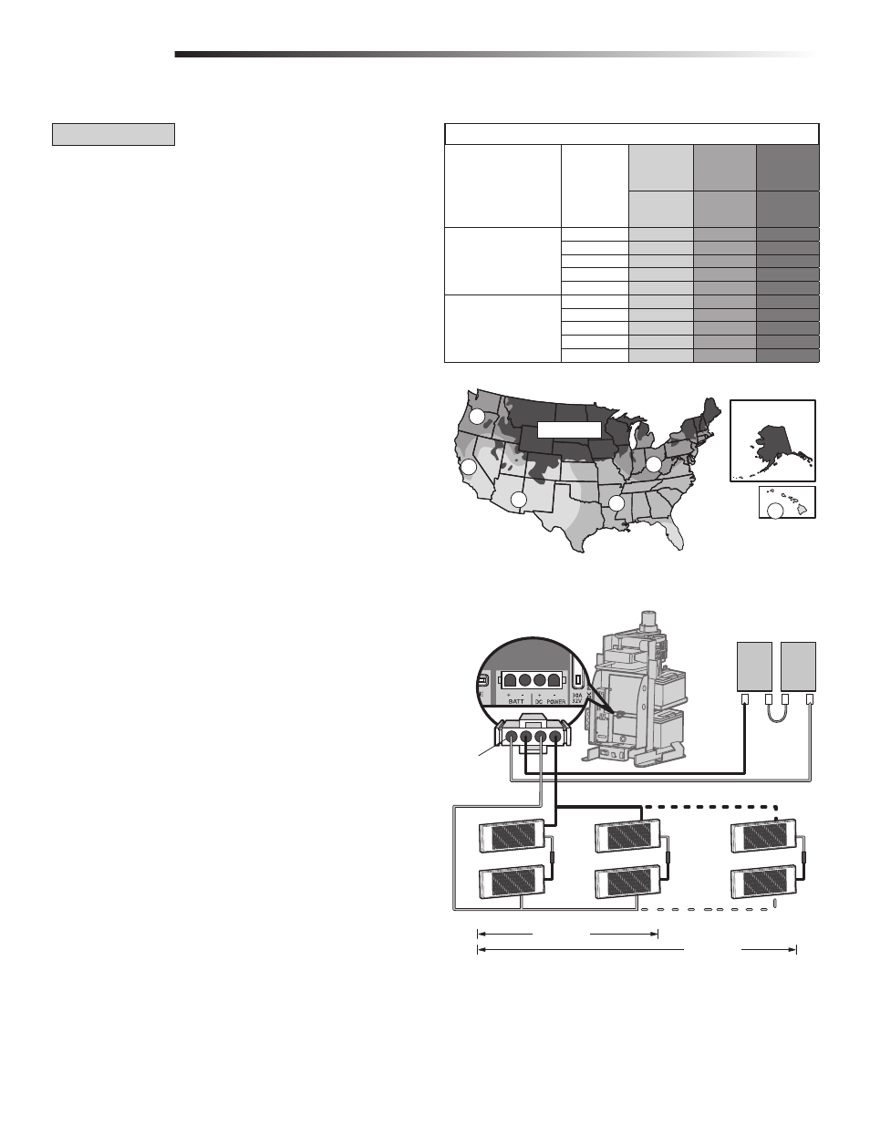
SOLAR PANEL(S)
NOT PROVIDED. SEE ACCESSORIES.
Solar Application requirements:
• A minimum of four 10W solar panels (Model SOLPNL10W12V). Configuration of
two sets of two 10W paralleled panels put in series.
• A maximum of six 10W solar panels (Model SOLPNL10W12V). Configuration of
three sets of two 10W paralleled panels put in series.
• Battery Tray (Model K10-36183).
• Solar Battery Harness (Model K94-36596).
• Two 33AH batteries, the standard 7AH batteries cannot be used.
• A heater cannot be used with a solar application.
For solar applications DO NOT use the expansion board and the wireless
dual gate feature. These features will substantially decrease the cycle
rate and standby time of the operator. We recommend LiftMaster low power
draw accessories to minimize power draw, refer to accessory page.
The solar panel(s) must be located in an open area clear of obstructions and shading
for the entire day. The gate operator is not supported in northern climates where
temperatures reach below -4˚F. This is due to cold weather and a reduced number of
hours of sunlight during the winter months. Cycle rate may vary from solar chart for
areas that reach below 32˚F. Solar panels should be cleaned on a regular basis for
best performance to ensure proper operation.
NOTE: Input solar power is 24 Vdc at 60 watts maximum.
1
Locate the J15 plug on the control board and unplug it from the control board
(it will not be used).
2
Install the new 33AH batteries using the tray as shown.
3
Connect the white jumper between the positive (+) terminal of one battery to
the negative terminal (-) of the other battery.
4
Route the battery wires (the longer set of wires) from the J15 plug (new wire
harness) through the lower, right, rear knockout (KO) in the electrical box. Use
the included adhesive wire clamps to route the wires up the right side of the
operator frame. Connect the red wire to the positive (+) terminal of one
battery. Connect the black wire to the negative (-) terminal of the other battery.
5
Connect the red wire (+) from one solar panel to the black wire (-) of the other
solar panel.
6
Connect the shorter red wire (+) from the J15 plug (new wire harness) labeled
DC Power to the red wire on one solar panel. Connect the shorter black (-) wire
from the J15 plug (new wire harness) labeled DC Power to the black wire from
the other solar panel.
7
Plug the J15 plug (new wire harness) into the J15 input on the control board.
NOTE: You may see a small spark when plugging the J15 plug into the board.
Proceed to the Dual Gate section (if applicable) or proceed to the Adjustment section.
NOT AVAILABLE
NOT AVAILABLE
1
1
2
3
2
3
NUMBER OF CYCLES PER DAY (SOLAR)
Swing Gate Installation
(12 ft. 800 lb. gate)
ACCESSORY
POWER
DRAW (mA)
ZONE 1
(6 Hrs
sunlight/day)
ZONE 2
(4 Hrs
sunlight/day)
ZONE 3
(2 Hrs
sunlight/day)
33AH Batteries
Required (2)
33AH Batteries
Required (2)
33AH Batteries
Required (2)
40W SOLAR PANEL
0
106
61
22
50
85
42
N/A
100
64
24
N/A
300
N/A
N/A
N/A
500
N/A
N/A
N/A
60W SOLAR PANEL
0
172
101
39
50
149
80
21
100
126
60
N/A
300
42
N/A
N/A
500
N/A
N/A
N/A
40W Solar panel
installation
60W Solar panel
installation
Black Wire (-)
33AH Batteries
Red Wire (+)
J15 Plug
(new wire harness,
Model K94-36596)
+
+
+
+
+
+
–
–
–
–
–
–
–
+
–
+
Red Wire (+)
Black Wire (-)
POWER WIRING CONTINUED...