Power wiring, Wiring – LiftMaster CSW24V High-Cycle Commercial DC Swing Gate Operator User Manual
Page 22
20
POWER WIRING
WIRING
POWER WIRING
This operator can be wired for either 120 Vac or 240 Vac or a solar
panel (not provided). Follow the directions according to your application.
For dual gate applications, power will have to be connected to each
operator. Main power supply and control wiring MUST be run in
separate conduits.
NOTE: If using an external receiver use shielded wire for the connections and
mount the receiver away from the operator to avoid interference with the operator.
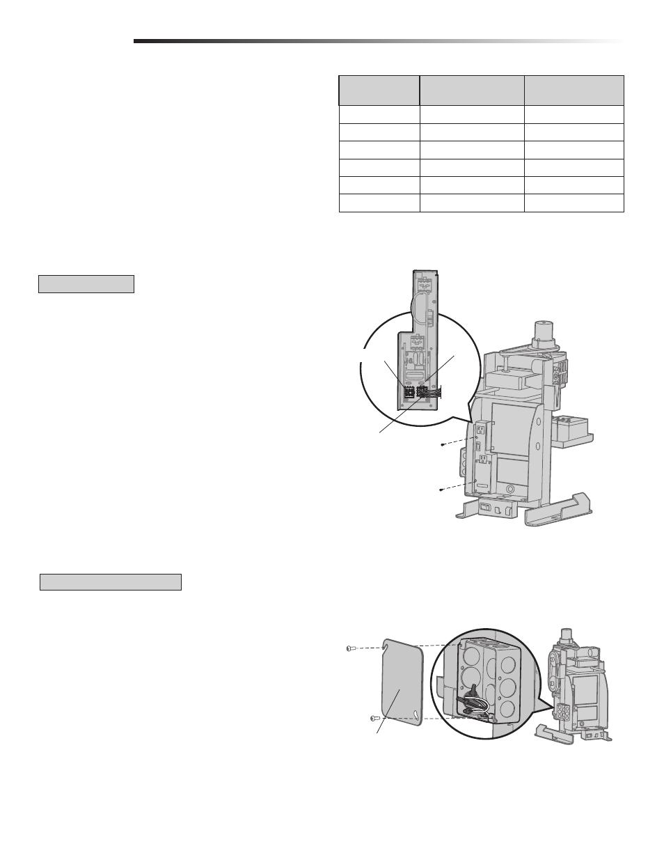
240 VAC ONLY
If using the 240 Vac option a heater cannot be used. The accessory outlet is disabled
and cannot be used with the 240 Vac option.
1
Remove the outlet housing from the electrical box by removing the
screws (2).
2
Pull the outlet housing out and locate the power wiring connector on the
EMI board.
3
Unplug the power wiring connector from the 120 Vac socket (factory default
location) and plug it into the 240 Vac socket.
4
Replace the outlet housing by securing with the screws. The operator is now set
for 240 Vac operation.
Outlet Housing
Power Wiring Connector
(120 Vac Socket, factory default)
240 Vac Socket
AMERICAN WIRE
GAUGE (AWG)
MAXIMUM WIRE
LENGTH (120 VAC)
MAXIMUM WIRE
LENGTH (240 VAC)
14
130 feet
260 feet
12
205 feet
410 feet
10
325 feet
650 feet
8
520 feet
1040 feet
6
825 feet
1650 feet
4
1312 feet
2624 feet
EMI Board
NOTE: Use copper conductors ONLY.
120 VAC AND 240 VAC
Junction Box Cover
1
Turn off the AC power from the main power source circuit breaker.
2
Run the AC power wires to the operator.
3
Remove the junction box cover.
4
Connect the green wire to the earth ground rod and AC ground using a wire
nut. NOTE: The earth ground rod can be grounded to the chassis.
5
Connect the white wire to NEUTRAL using a wire nut.
6
Connect the black wire to HOT using a wire nut.
7
Replace the junction box cover. Ensure the wires are not pinched.