System schematic diagrams – King Electric SST 3 User Manual
Page 10
Adjustable Electronic Thermostat TRACON
®
Model SST–3
(P/N 24492)
Instruction Manual
24494
Rev. -
04/12
(800) 234-4239
http: www.networketi.com
Environmental Technology, Inc.
10 of 28
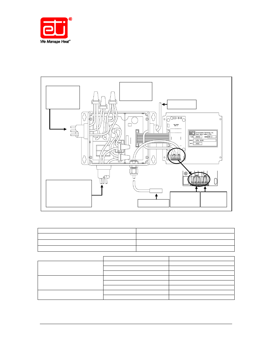
SYSTEM SCHEMATIC DIAGRAMS
Figure 2 presents a schematic diagram of the SST–3.
* See Page 11.
Figure 2. REPRESENTATIVE SST–3 SYSTEM SCHEMATIC.
POWER Cable (provided by customer)
Size for 30 Amp maximum load
HEATER Cable (provided by customer)
Size to system load
ALARM RELAY Wiring (provided by customer)*
No larger than #18 AWG jacketed, 3-conductor*
TEMPERATURE PROBE Wiring
#18 AWG jacketed, 2-conductor
* See Page 11.
Wire Lead
Connect To:
INPUT Power
(provided by customer)
Line 1
Black
Line 2 / Neutral
White
Ground Green
OUTPUT To Heater
(provided by customer)
Heater Load 1
Yellow
Heater Load 2
Yellow
Heater Ground (Shield)
Green
OUTPUT To Alarm Relay*
(provided by customer)
Hook-Up Wire 1
COM
Hook-Up Wire 2
Either NC OR NO*
* See Page 11.
Table 1. CABLE RATINGS AND CONNECTIONS.
Alarm Relay
Leads*
Temp.
Probe
Leads
Temp. Probe
Alarm Relay
200–277 VAC
50/60 Hz
30 Amp Max.
Input Power
Line/Black
Neutral/White
Ground/Green
To Heater Cable
Heater Load 1/Yellow
Heater Load 2/Yellow
Heater Ground
(Shield)/Green