KB Electronics KBPW-240D User Manual
Page 6
D. Motor Current – Jumper J2 is factory set for 7.5 Amp motors. For lower current motors,
set jumper J2 to the corresponding motor current as described in Section IVB, on page 9.
Note: The factory setting for Current Limit is 150% of the nominal current setting (exam-
ple: if jumper J2 is set to “5A” position, the CL trimpot is calibrated for 7.5 Amps).
E. Trimpot Settings – All trimpots have been factory set as shown in Figure 1, on page 4.
Trimpots may be readjusted as described in Section VIII, on page 12.
F. Diagnostic LEDs – After power has been applied, observe the LEDs to verify proper con-
trol function as described in Section IX, on page 13.
G. Start/Stop Switch – The control is supplied with a prewired Start/Stop switch as
described in Section IIIG, on page 8. This switch must be used to start the control each
time the AC power is lost or the control shuts down in TCL. To override this function, see
Section IIIG, on page 8.
1.
For low current operation, remove resistor R35 as described in section IVB, on page 9
2.
Step-down operation – Motor may have reduced brush life – Consult motor manufacturer.
3
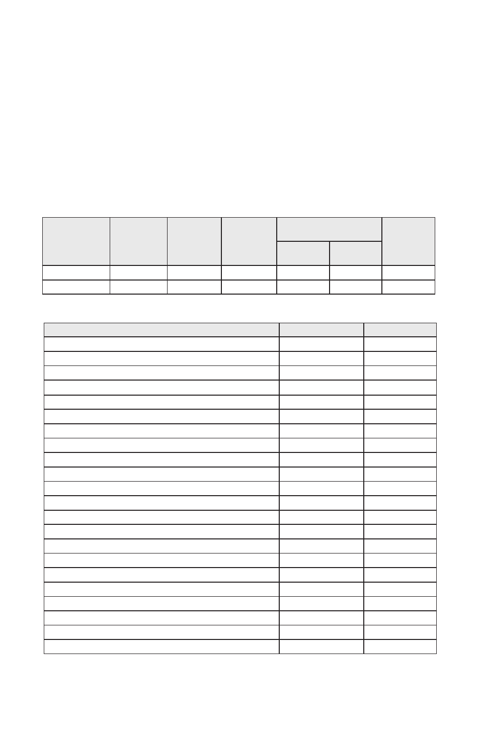
115
AC Line Voltage
(±10%, 50/60 Hz)
(Volts AC)
Motor Voltage
(Volts DC)
Maximum AC
Line Current
(Amps RMS)
Maximum
Load Current
(Amps DC)
Maximum Horsepower
HP, (kW)
SCR Rated
Motors
PWM Rated
Motors
3/4, (0.5)
208 – 230
0 – 90, 130
11.5
7.5
1, (0.75)
Field Voltage
(Volts DC)
200
100
7.5
2, (1.5)
1
1
⁄
2
, (1)
11.5
0 – 180, 260
TABLE 1 – ELECTRICAL RATINGS
0
100
Specification
Factory Setting
Parameter
0 – 50
Operating Frequency (kHz)
0.5 – 10
Operating Temperature Range at Full Rating (ºC)
>16
–
Current Range (High Scale) (Amps DC)
0 – 50
–
1.7, 2.5, 3.5, 5.0, 7.5
7.5
Current Range (Low Scale) (Amps DC)1
ACCEL and DECEL Range (Seconds)
Jog Speed (% Base Speed)
MIN Speed Range (% Base Speed [90VDC & 180VDC Motors])
MAX Speed Range (% Base Speed [90VDC & 180VDC Motors])
IR Comp Range at 90 Volts DC Output (∆Volts DC at Full Load)
IR Comp Range at 180 Volts DC Output (∆Volts DC at Full Load)
CL Range (% Range Setting)
Timed Current Limit (TCL) Range (Seconds)
AC Line Input Voltage (Volts AC, ±10%, 50/60 Hz)
Armature Voltage Range at 115 Volts AC Line Input (Volts DC)
Armature Voltage Range at 208/230 Volts AC Line Input (Volts DC)
Field Voltage at 115 Volts AC Line Input (Volts DC)
–
–
Field Voltage at 208/230 Volts AC Line Input (Volts DC)
Speed Range (Ratio)
50:1
0.2, 0.3, 0.4, 0.5, 0.8
0.5 – 10
0 – 30
50 – 140
0 – 15
0 – 30
0 – 200
115 – 208/230
0 – 130
0 – 130 2, 0 – 260
100/50
200/100
150
–
1
15
4
8
5
–
90
90
–
Voltage Following Linearity (% Base Speed)
±0.5
–
TABLE 2 – GENERAL PERFORMANCE SPECIFICATIONS
AC Line Regulation (% Base Speed)
0.5
–
Armature Feedback Load Regulation (% Base Speed)
1
–
Tach-Generator Feedback Load Regulation (% Set Speed)
1
–