KB Electronics KBPW-240D User Manual
Page 12
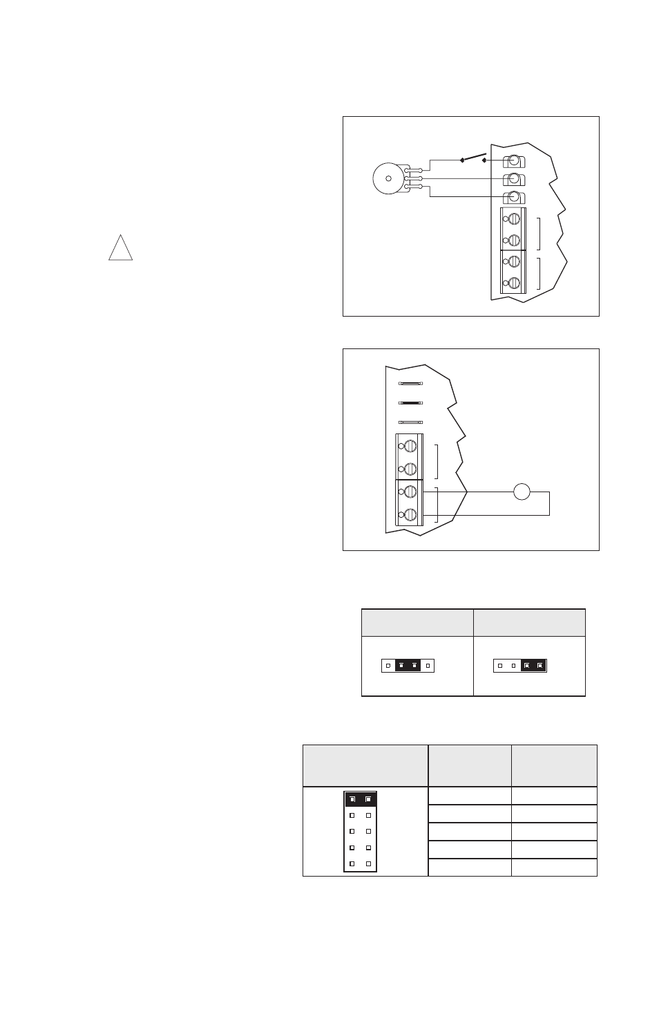
K. Enable Connections – The control can also be started and stopped with an Enable cir-
cuit (close to start). See Figure 10. This circuit functions opposite to that of the Inhibit cir-
cuit (open to start). The Enable function
is established by wiring a switch in series
with the violet main speed potentiometer
lead which connects to the P3 terminal.
When the Enable switch is closed, the
control will accelerate to the main speed
potentiometer setting. When the Enable
switch is opened, the control will coast to
stop.
Warning! Do not use Enable as
a safety disconnect. Use only
the AC line for this purpose. P3 ter-
minal is not isolated and is not to be
Earth grounded.
L. DC Tach-Generator Connection – Wire
the tach-generator to T+ (+) and T- (-)
terminals of TB4 as shown in Figure 11.
Jumper J1 must be in “T” position.
Jumper J4 must be in “7V” position for 7
Volt per 1000 RPM tach-generators or
“50V” position for 50 Volt per 1000 RPM
tach-generators. See section IVD on
page 11.
Note: When using a tach-generator, the
IR trimpot should be set fully counter-
clockwise.
IV.
SETTING SELECTABLE JUMPERS
The KBPW-240D has customer selectable
jumpers which must be set before the con-
trol can be used. See Figure 1, on page 4
for location of jumpers.
A. Motor Voltage Selection (J1) – Jumper
J1 is factory set to “90V” position for 90
Volt SCR rated motors (or 130 Volt
PWM rated motors). For 180 Volt SCR
rated motors (or 220 Volt PWM rated
motors), set jumper J1 to “180V” posi-
tion. See Figure 12.
Note: If jumper J1 is set to “T”
position, a tach-generator must
be wired to TB3. If a tach-gen-
erator is not used, jumper J1
must be in either “90V” or “180V”
position. If jumper J1 is in “T”
position and a tach-generator is
not used, the motor will acceler-
ate to full speed and the main
speed potentiometer will not
control speed.
B. Motor Current Selection (J2) –
Jumper J2 is factory set to “7.5A”
position for 7.5 Amp motors.
*Note: For low (L) motor current range settings (0.8A, 0.5A, 0.4A,
0.3A and 0.2A), it is necessary to remove resistor R35 by cutting it
out of the circuit as shown in figure 14 on page 10.
9
(CLOSE TO START)
SWITCH OR RELAY
Orange
White
Violet
Potentiometer
Main Speed
TACH
P3
P2
P1
TB4
K2
K1
TB3
T-
RELAY
T+
FIGURE 10 – ENABLE CIRCUIT
!
G
DC TACH-GENERATOR
+
-
P3
P1
P2
K2
T-
TB3
RELAY
K1
TB4
T+
TACH
FIGURE 11 – DC TACH-GENERATOR
90V
180V
T
J1
90V
J1
180V
T
J1 Set for 90 Volt Motors
(Factory Setting)
J1 Set for 180 Volt Motors
FIGURE 12 – MOTOR VOLTAGE SELECTION
0.2
7.5
5.0
3.5
2.5
1.7
0.8
0.5
0.4
0.3
Low Scale
Current Range*
(Amps DC)
High Scale
Current Range
(Amps DC)
J2 Set for 7.5 Amp Motor
(Factory Setting)
FIGURE 13 – MOTOR CURRENT SELECTION