KB Electronics Installs on end of KBVF User Manual
Page 8
“The Right Control for Your Application.”
12095 NW 39 Street, Coral Springs, FL 33065-2516
Telephone: 954-346-4900; Fax: 954-346-3377
KB Electronics, Inc.
www.KBelectronics.com
SIVFR Signal Isolator and Run/Fault Relay (Part No 9597)
SIVFR Signal Isolator and Run/Fault Relay (Part No 9597)
SIVFR Signal Isolator and Run/Fault Relay (Part No 9597)
SIVFR Signal Isolator and Run/Fault Relay (Part No 9597)
Supplemental Information for Installation and Operation Manual Part No. A40264
Supplemental Information for Installation and Operation Manual Part No. A40264
Supplemental Information for Installation and Operation Manual Part No. A40264
Supplemental Information for Installation and Operation Manual Part No. A40264
(A42132) – Rev. B01 – 9/18/2006 – Z3017B01
Page 8 of 8
Table 2
Drive Operating Condition and Run/Fault Relay Contact Status
Relay Contact Status (Terminals K1 and K2 of TB2)
Run Relay Operation
(J4 Installed in “RUN” Position)
(Factory Setting)
Fault Relay Operation
(J4 Installed in “FAULT” Position)
Drive
Operating Condition
J2 Installed in “NO” Position
(Factory Setting)
J2 Installed in “NC” Position
J2 Installed in “NO” Position
(Factory Setting)
J2 Installed in “NC” Position
Power Off
(Main Power Disconnected)
Open
Closed
Open
Closed
Run Mode*
(Normal Drive Operation)
Closed
Open
Closed
Open
Stop Mode*
(Selected by Operator)
Open
Closed
Closed
Open
Fault**
(Drive Tripped)
Open
Closed
Open
Closed
*Run Mode or Stop Mode is selected using the Forward-Stop-Reverse Switch. **Fault: Overload, I
2
t, Short Circuit, Undervoltage, and Overvoltage.
5
5
5
5
OPTIONAL FINGER-SAFE PANEL
OPTIONAL FINGER-SAFE PANEL
OPTIONAL FINGER-SAFE PANEL
OPTIONAL FINGER-SAFE PANEL
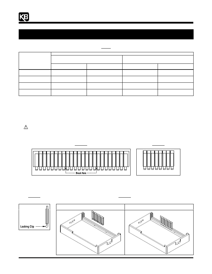
The SIVFR is supplied with a finger-safe panel which may be used with the enclosure cover to close the unused exposed area of the
SIVFR between Terminal Blocks TB1 and TB2. The finger-safe panel is a 24-segment panel. Only an 8-segment piece is needed for the
SIVFR. The finger-safe panel may be separated into three equal size pieces. See Figure 19.
WARNING! Use caution and wear eye protection when snapping off or cutting off sections of the finger-safe panel.
5.1
Segmenting the Finger-Safe Panel: By bending the finger-safe panel back and forth at the breakaway points, snap off an
8-segment piece (1¼” in length). See Figure 20.
Figure 19
24-Segment Finger-Safe Panel
Figure 20
8-Segment Finger-Safe Panel
5.2
Installing the 8-Segment Finger-Safe Panel: Notice the locking clip on the side view of the finger-safe panel, as shown in Figure
21. Install the 8-segment panel into the enclosure cover with the locking clip facing toward the center of the enclosure cover, as
shown in Figure 22. Also see Figure 2, on page 2.
Figure 21
Side View of the
Finger-Safe Panel
Figure 22
Installing the 8-Segment Finger-Safe Panel
Onto the Enclosure Cover
8-Segment Finger-Safe Panel Aligned
with the Enclosure Cover
8-Segment Finger-Safe Panel Installed
Onto the Enclosure Cover