KB Electronics Installs on end of KBVF User Manual
Page 19
B.
MOUNTING THE SIVF ONTO THE KBVF
See figure 3, SIVF Mounting Diagram.
See figures 4A and 4B, SIVF Mechanical Specifications, on pages 7 and 8.
The SIVF is installed onto the KBVF using (2) two 6-32 X 1/2” screws provided.
Note: The screws are a combination head type which allow the use of a readily avail-
able #1 or #2 phillips or slotted head screwdriver.
Note: Before installing the SIVF be sure the wiring to the KBVF has been completed.
See section II, Installation Instructions, on page 3
1.
Align the SIVF mounting holes with the tapped holes on the KBVF heat sink and
insert the screws through the SIVF mounting holes.
2.
Using a screwdriver, fasten both screws until the SIVF is secured to the KBVF (8
in-lbs max). Do not over tighten screws or damage may result to SIVF cover.
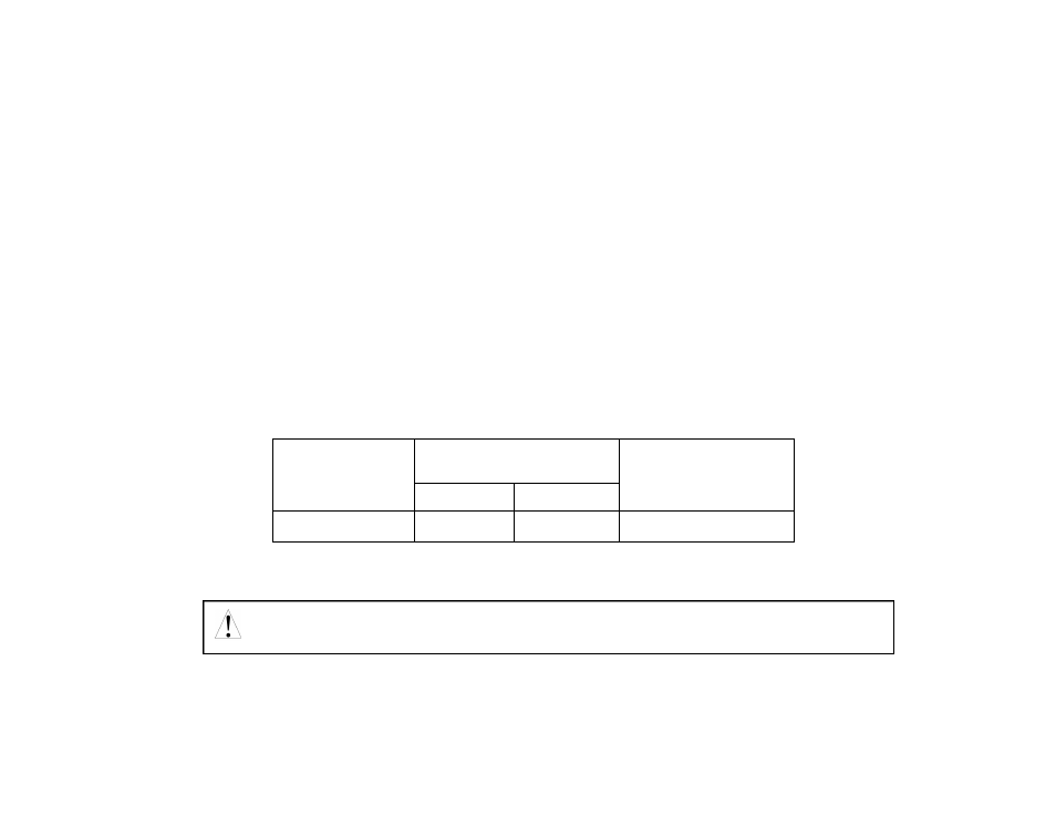
TABLE 2 – TERMINAL BLOCK WIRING INFORMATION
III.
CONNECTIONS TO THE SIVF
9
Safety Warning! Do not use FWD-STOP-REV contacts as a safety disconnect since
they are not fail-safe. Use only the AC line for this purpose.
Connection
Designation
Supply Wire Gauge
(AWG – Cu)
Minimum
Maximum
Maximum
Tightening
Torque (in-lbs)
Logic Connections
24
14
3.5