KB Electronics Installs on end of KBVF User Manual
Page 5
“The Right Control for Your Application.”
12095 NW 39 Street, Coral Springs, FL 33065-2516
Telephone: 954-346-4900; Fax: 954-346-3377
KB Electronics, Inc.
www.KBelectronics.com
SIVFR Signal Isolator and Run/Fault Relay (Part No 9597)
SIVFR Signal Isolator and Run/Fault Relay (Part No 9597)
SIVFR Signal Isolator and Run/Fault Relay (Part No 9597)
SIVFR Signal Isolator and Run/Fault Relay (Part No 9597)
Supplemental Information for Installation and Operation Manual Part No. A40264
Supplemental Information for Installation and Operation Manual Part No. A40264
Supplemental Information for Installation and Operation Manual Part No. A40264
Supplemental Information for Installation and Operation Manual Part No. A40264
(A42132) – Rev. B01 – 9/18/2006 – Z3017B01
Page 5 of 8
1.6
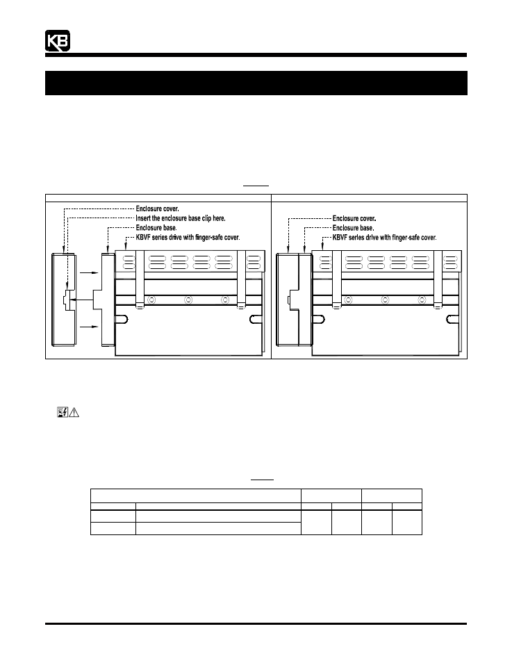
INSTALLING THE ENCLOSURE COVER: After all wiring is complete and the SIVFR is properly mounted onto the KBVF, install the
enclosure cover. See Section 5, on page 8, for installing the finger-safe panel.
Orient the enclosure cover such that the label is upright (and the wider opening of the enclosure cover is at the top). Align both clips
on the enclosure base with both slots on the enclosure cover. Gently push on the enclosure cover until both clips are fully engaged.
See Figure 8.
Note: Be sure the “handles” of Jumpers J1, J2, J4, J5 remain inside the enclosure and they do not get crimped while installing the enclosure cover.
Figure 8
Installing the Enclosure Cover
SIVFR Mounted Onto the KBVF
Enclosure Cover Installed Onto the SIVFR
2
2
2
2
WIRING INSTRUCTIONS
WIRING INSTRUCTIONS
WIRING INSTRUCTIONS
WIRING INSTRUCTIONS
See Table 1, for the wire size and recommended tightening torque for Terminal Blocks TB1 and TB2 on the SIVFR.
WARNING! Read Safety Warning, on page 1 of the SIVF manual, before using the drive. Disconnect main power when
making connections to the drive.
Application Note: To avoid erratic operation, do not bundle the AC line and motor wires together or with wires from signal following,
start/stop contacts, or any other signal wires. Also, do not bundle motor wires from multiple drives in the same conduit. Use shielded
cables on all signal wiring over 12" (30 cm). The shield should be earth grounded on the drive side only. Wire the drive in accordance
with the National Electrical Code requirements and other local codes that may apply.
Table 1
Terminal Block Wiring Information
Terminal Block
Maximum
Wire Size (Cu)
Recommended
Tightening Torque
Designation
Description
AWG
mm
2
in-lbs
kg-cm
TB1
Main Speed Potentiometer, Signal Input, and Direction Switch
TB2
Run/Fault Relay Output Contacts
16
1.3
3.5
4