KB Electronics Installs on end of KBVF User Manual
Page 2
“The Right Control for Your Application.”
12095 NW 39 Street, Coral Springs, FL 33065-2516
Telephone: 954-346-4900; Fax: 954-346-3377
KB Electronics, Inc.
www.KBelectronics.com
SIVFR Signal Isolator and Run/Fault Relay (Part No 9597)
SIVFR Signal Isolator and Run/Fault Relay (Part No 9597)
SIVFR Signal Isolator and Run/Fault Relay (Part No 9597)
SIVFR Signal Isolator and Run/Fault Relay (Part No 9597)
Supplemental Information for Installation and Operation Manual Part No. A40264
Supplemental Information for Installation and Operation Manual Part No. A40264
Supplemental Information for Installation and Operation Manual Part No. A40264
Supplemental Information for Installation and Operation Manual Part No. A40264
(A42132) – Rev. B01 – 9/18/2006 – Z3017B01
Page 2 of 8
1
1
1
1
INSTALLATION INSTRUCTIONS
INSTALLATION INSTRUCTIONS
INSTALLATION INSTRUCTIONS
INSTALLATION INSTRUCTIONS
WARNING! High voltage is present while LEDs are illuminated. Before wiring the SIVFR to the KBVF, disconnect all power to the
KBVF and wait until the "PWR" and "ST" LEDs are no longer illuminated.
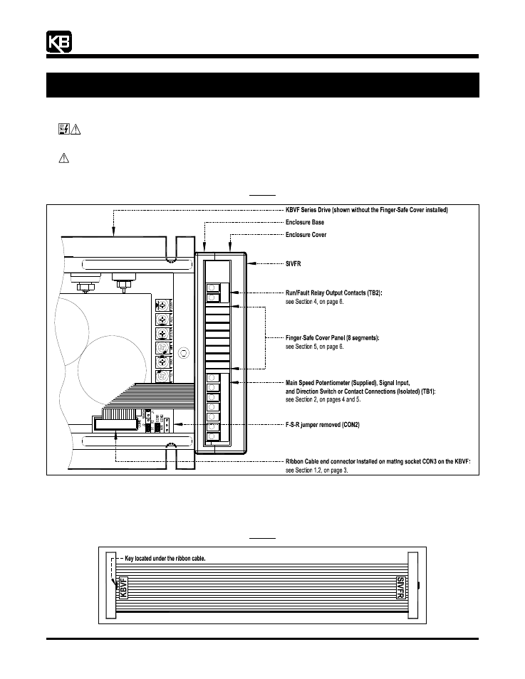
CAUTION! Before wiring and mounting the SIVFR, remove the jumper that is installed on CON2 (F-S-R) on the KBVF. Since
this jumper selects motor direction, removing it will prevent the motor from rotating, should the ribbon cable ever be
inadvertently disconnected while the drive is running. See Figure 2.
Figure 2
SIVFR Installation Diagram
F
-
S
-
R
1.1
RIBBON CABLE: Notice the location of the keys and labels on each end connector of the ribbon cable, as shown in Figure 3. The
end connector labeled “KBVF” installs into the mating socket on the KBVF (CON3), as described in Section 1.2, on page 3. The end
connector labeled “SIVFR” installs into the mating socket on the SIVFR (CON1), as described in Section 1.4, on page 4.
Figure 3
Ribbon Cable