KB Electronics Installs on end of KBVF User Manual
Page 21
11
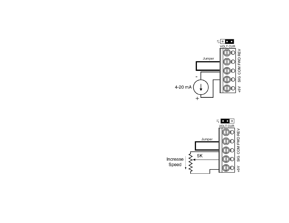
Be sure the positive (+) signal is
connected to “SIG” terminal and
the negative (-) is connected to
the “COM” terminal.
When a 4mA DC signal is applied, the motor will operate
at the minimum set speed (set by the MIN trimpot on
the SIVF). When a 20mA DC signal is applied, the
motor will operate at the maximum set speed (set by
the MAX trimpot on the SIVF)
B.
Potentiometer Operation – Uses a potentiome-
ter to vary motor speed.
Set J1 to “VOLT” position and connect the 5K potentiometer
to TB1 terminals marked “SIG” (wiper of
potentiometer), “+5” (high side of poten-
tiometer), and “COM” (low side of poten-
tiometer). See figure 7 Potentiometer
Connection. When the potentiometer is set to 0% (fully counterclock-
wise), the motor will operate at the minimum set speed (set by
the MIN trimpot on the SIVF). When the potentiometer is
set to 100% (full clockwise position) the motor will operate
at full speed (set by the MAX trimpot on the SIVF).
C.
Unidirectional Operation
To operate the control in forward, install a
jumper between “FWD” and “COM” terminals of
the SIVF
To operate the control in reverse, install a jumper between “REV” and “COM” termi-
Figure 6 – Current Following Connection
(Jumper J1 in “CUR” Position)
Figure 7 – Potentiometer Connection
(Jumper J1 in “VOLT” Position)