IDEC SG4 Type 4 Finger & Hand User Manual
Page 33
Instruction
Manual
SG4-B
Series
29
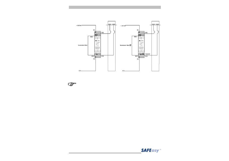
Example: connection to the safety relay.
Fig. 16
The figures show the connection between the safety light curtains
and the safety relay of the SE-SR2 series functioning in the
Automatic Restart mode (left side) and Manual Restart with
monitoring (right side).
Do not use varistors, RC circuits or LEDs in parallel at relay inputs
or in series at OSSD outputs.
The OSSD1 and OSSD2 safety contacts cannot be connected in
series or in parallel, but can be used separately (Fig.17),
conforming to the plant’s safety requirements.
If one of these configurations is erroneously used, the device enters
into the output failure condition (see section 7 “Diagnostic functions”).