C. status menu – HTP 850 LPHL User Manual
Page 52
52
LP- 205 REV. 3.28.14
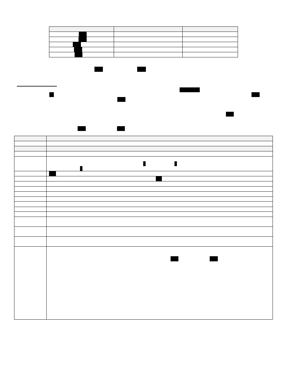
Function
Display
Press
{S3}
once
Boiler Temperature Set Point
C
Press
{S3}
twice
Boiler Differential Set Point
Ch
Press
{S3}
three times
Indirect Temperature Set Point
D
Press
{S3}
four times
Indirect Differential Set Point
DH
Press
{S3}
five times
Temperature Measurement Units
f
Table 9
– Additional Setting Options
To decrease or increase values, press
{S1}
to decrease and
{S2}
to increase. Changes are directly stored and the display returns
to normal mode after one minute.
C. STATUS MENU
Installers are also able to check the current status of the boiler parameters by pressing
{S4/Reset}
for 3 seconds. Once activated, the
display will show
d1
alternating value of the actual supply temperature. To change the next function value, the user can press
{S1}
(alternating down to previous function value) or press
{S4}
(alternating up to the next value). Actual values are displayed for each
function.
Listed below are the values which can be displayed. These values cannot be changed. To exit this menu, press
{S3}
to resume normal
operation.
To toggle between values press
{S1}
to go down and
{S4}
to go up.
Function
Value
|d1|
Actual temperature from supply sensor
Function
Value
|d2|
Actual temperature from return sensor
|d3|
Indirect temperature will be displayed if an indirect fired water heater and a 7250P-325 sensor is connected. If a
mechanical control is used, the control will display
0
for closed and
1
for open. If a DHW tank is not connected, the
display will read
0
. NOTE: If unit is set up as master, the system sensor will be visible.
|d4|
320
Not used.
|d5|
Actual temperature from the outdoor sensor if connected
NC
.
|d6|
Actual fan speed multiplied by 10 (Example: If fan speed displayed is |410| RPM x 10 = 4100 actual fan speed)
|d7|
Actual ionization current read from flame rectification probe
|d8|
Actual status of the central heating circulator - Off = |0|, On = |1|.
|d9|
Actual status of the indirect fired circulator - Off = |0|, On = |1|.
|d10|
Actual status of bus communication |co| = connected, |nc| = not connected
|d11|
Central heating set point
|d12|
Power on hours in thousands (display will not read until 100 hrs). Example: Display number x 1000 = Power on hours.
|d13|
Total central heat hours in thousands (display will not read until 100 hrs). Example: Display number x 1000 = Power
on hours.
|d14|
Total domestic hot water hours in thousands (display will not read until 100 hrs.) Example: Display number x 1000 =
Power on hours.
|d15|
Passed ignition attempts in thousands (display will not read until 100 ignition attempts).
Example: Display number x 1000 = ignition attempts. Display showing 12.3 x 1000 = 12300 ignition attempts.
|d16|
This function only becomes active when boiler is set as the Master. It allows the user to monitor the system pump
connected to the Master Boiler and the connected boilers (Followers) in a multiple boiler installation. Each boiler firing
output percentage is displayed. To toggle between values, press
{S1}
to go down and
{S4}
to go up.
The first function you will see is:
System Pump - (0 = Off, 1 = On)
|P0| - Master Boiler - Alternating (0-100 Percentage firing rate)
|P1| - Follower Boiler #1
– Alternating (0-100 Percentage firing rate)
|P2| - Follower Boiler #2
– Alternating (0-100 Percentage firing rate)
|P3| - Follower Boiler #3
– Alternating (0-100 Percentage firing rate)
|P4| - Follower Boiler #4
– Alternating (0-100 Percentage firing rate)
|P5| - Follower Boiler #5
– Alternating (0-100 Percentage firing rate)
|P6| - Follower Boiler #6
– Alternating (0-100 Percentage firing rate)
|P7| - Follower Boiler #7
– Alternating (0-100 Percentage firing rate
NOTE: If you toggle beyond parameters of connected boilers, the display will go into the next function value.
Table 10
– Boiler Status Menu