G. circulator sizing – HTP 850 LPHL User Manual
Page 17
17
LP- 205 REV. 3.28.14
4. Install a back flow preventer on the cold feed make-up water line.
5. Install a pressure reducing valve on the cold feed make-up water line (15 PSI nominal on the system return). Check temperature and
pressure gauge when operating. It should read a minimum pressure of 12 PSI.
6. Install a circulator as shown in piping details (this section). Make sure the circulator is properly sized for the system and friction loss.
7. Install an expansion tank on the system supply. Consult the tank manufacturer’s instructions for specific information relating to
expansion tank installation. Size the expansion tank for the required system volume and capacity.
8. Install an air elimination device on the system supply.
9. Install a drain valve at the lowest point of the system. NOTE: The boiler cannot be drained completely of water without purging the
unit with an air pressure of 15 PSI.
10. The relief valve is installed at the factory. A pipe discharge line should be installed to discharge 6” above the drain in the event of
pressure relief. The pipe size must be the same size as the relief valve outlet. NEVER BLOCK THE OUTLET OF THE SAFETY
RELIEF VALVE.
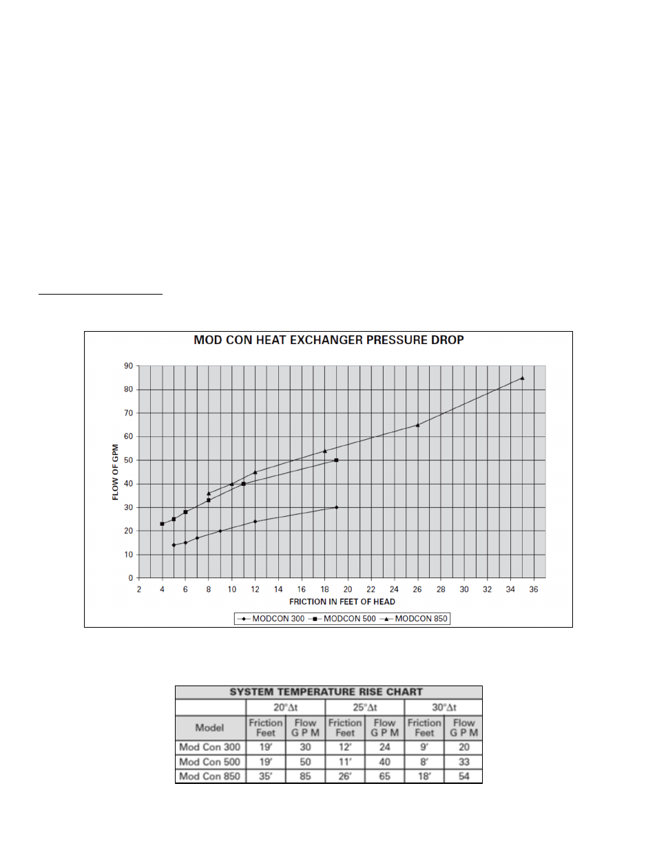
G. CIRCULATOR SIZING
The boiler heat exchanger does have a pressure drop which must be considered in system design. Refer to the graph in Figure 6 for
pressure drop through the boiler heat exchanger.
Figure 6
– Heat Exchanger Pressure Drop Chart
The chart below represents the various system design temperature rise through the boiler, along with respective flows and friction loss
which will aid in circulator selection.
Table 3
– Temperature Rise Chart